


The Heat Pump (HP) technology is used to produce heating water for household use. If the grid supply is decarbonised, using HP allows to significantly reduce the carbon dioxide emissions, compared to traditional technologies such as boiler [1]. Coefficient of Performance (COP) is a key point in product marketing and energy labelling. There are different test standards for HP Water Heaters (HPWHs) in use in different regions of the world. As a result, manufacturers have to undertake a different set of tests for each economy where they sell their products. This adds to product cost and slows the development of the global market. A way to avoid this is to develop a HPWH COP model based on a limited number of tests. Ideally, the model allows local regulators to determine the COP of products under local test conditions, without conducting additional physical tests.
The principles of HPWH operation are well understood and some existing models allow HPWH performance to be accurately simulated. Modelling a heat pump is generally divided into two categories: polynomial fits and semi-empirical. In the first category, the correlations are fitted to experimental data as the models presented in [2]-[4]. The semi empirical approach, for instance the model used in the papers [5]-[7], is based on thermodynamic evolutions of the working fluid through the components of the heat pump. The model requires data to calibrate its parameters. Some models can be used only for steady state working conditions, such as the model presented in [8], while others allow to study dynamic conditions including the start-up phase and defrosting phase [9], [10]. The common point of these cited works is that the models are used to predict the COP at an ambient condition which remains constant during the simulation. It is also possible to estimate the average COP over a season during which the ambient condition changes continuously in time [11], [12].
Reviews are presented in [13]-[15] on simulation techniques for heat pump systems, not only the well-established techniques but also the developing techniques such as the Artificial Neural Network (ANN) technique [16] and the fuzzy theory [17]. It should be noted that all these models are relatively sophisticated, require significant input data [13] and thus are difficult to use in a regulatory environment.
In this context, it is interesting to study the possibility of developing a simplified performance model built from a number of experimental test results and then to examine the predictive capability of the model developed.
In general, COPins depends mainly on the operating conditions, including the ambient temperature and the water temperature. During a standard performance test, the ambient temperature is set to be constant but the tank temperature varies. In this situation, the coefficient of performance is defined by integration over the test duration:
where the subscripts int, i and f refer to integrated, initial moment and final moment respectively.
If the heat-up phase without a draw off cycle is considered in isolation, the heating power can be calculated from the tank temperature variation as follows:
where:
m is the water mass contained in the tank;
cp is the specific heat capacity of the water;
Tt is the tank water temperature (
t is then derivative of temperature as function of time).
In addition, the principal variable can be changed from time to the tank water temperature as follows:
because m and cp are practically constant. (Eq. 4) allows the COPint to be calculated if the variation of COPins as a function of Tt is known. The next section presents some correlation-based models of COPins as a function of Tt, drawn from the scientific literature.
where a1, a2, a3 are constants; and the subscripts d, w and dew refer to dry bulb, wet bulb and dew point of the surrounding air temperature, respectively. This correlation model was validated using experimental data from two HPWHs: one with a wrap-around condenser coil and the other with an external condenser. The tests were carried out under different ambient conditions without a draw-off cycle. Compared to the measured values, the correlation model gave an average error of 4% with a maximum error of about 15%.
During the development of the Australian/New Zealand Standard (AS/NZS) [19], a number of alternative correlation functions, including the model presented above, were investigated from which the following model was selected:
In another analysis of an air-cooled HPWH, known as the EnergyPlus simulation [20], the following correlation is proposed:
where the c coefficients are constants, and Ta is either the dry bulb temperature or the wet bulb temperature of the ambient air.
It should be noted that all these correlations were developed to predict the HPWH performance for the whole range of operating conditions. For this reason, they require much experimental data to determine correctly the coefficients. In addition, they were only tested in the heat-up phase, their predictive capability is then not known during a whole cycle including both heat-up and draw-off phases.
Specifically, the accuracy of the AS/NZS model of COP, which is the last developed instantaneous COP model, will be tested against a HPWH data. This model contains 4 variables of temperature. It is worth noting that the air temperatures (Td, Tw and Tdew) are generally correlated in the test standards.
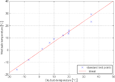
Figure 1 shows dry bulb and wet bulb temperatures collected from different standards, the coefficient of determination R2 is equal to 0.98. Therefore including all 3 air temperatures in the correlation model presents a degree of redundancy and is therefore probably inappropriate. For this reason, we propose to test a three-variable model based on Td and Tw and a two-variable based only on Tw. In summary, the current study investigates the following correlation models:
Coincident wet bulb and dry bulb temperatures of the different test standards, including Australian/New Zealand, US, Japanese, European and Korean standards [19], [21]-[24]
The coefficients can be determined by regression using physical test data. While the air temperatures are obtained from measurements made of the ambient air, the most appropriate data used to define the water temperature Tt varies with the HP system technology. In general, Tt should be the average water temperature in the condenser. In the case of separate HPWHs that have a circulation pump between the tank and the HP, Tt is a function of the temperature at the inlet and outlet of the condenser. For integral condenser HPWHs, the definition of the tank water temperature should be based on the average water temperature over the depth of the condenser coil positioned in the tank or wrapped around the tank. Due to the difficulty of applying this definition in real life, an alternative way is to consider Tt as the tank water temperature averaged over the whole depth of the tank. In principle this could introduce significant error if the temperature at the condenser inlet significantly differs from the water tank temperature (for separate tank-HP systems) or if the tank is stratified (for integral condenser HPs).
This section illustrates how a HPWH COP model can be developed and investigates the precision of the models derived.
Figure 2 summarises the main modelling steps, which are subsequently explained in the text.
Methodology for modelling HPWH energy performanc
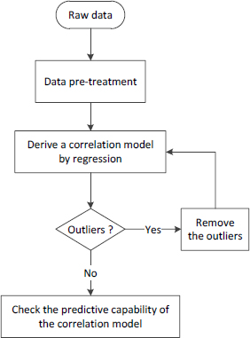
Once the outliers have been excluded, a regression model can then be refitted to the data. It is for this reason that an iterative loop is required to repeat the regression until there are no outliers left.
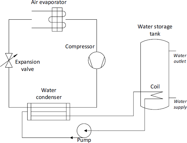
Scheme of the tested HPWH
Among existing international performance test standards, the AS/NZS standard [19] is the standard that requires the greatest number of different test conditions during the heat-up phase (Table 1). So, in principle a correlation model fitted to the AS/NZS test data could help in predicting heat-up phase performance of other international test standards. For this reason, regression models are derived from a set of four AS/NZS standard tests applied to a HPWH, according to the methodology proposed in Figure 2.
Summary of AS/NZS standard test data
| Test number | Air temperature | Average water temperature | ||
|---|---|---|---|---|
| Dry bulb | Wet bulb | At the beginning of test | At the end of test | |
| 1 | 10 | 9 | 9.5 | 58.4 |
| 2 | 20 | 16 | 14.6 | 57.4 |
| 3 | 35 | 23 | 24.4 | 54.8 |
| 4 | 35 | 29 | 24.3 | 54.2 |
The predictive capability of the models obtained is then verified using test data for the same HPWH measured under the following standards: USA [21], Europe [22] and Japan [23]. The assessment only considers and applies to the heat-up phase without drawoff. The predictive capability of the correlation models are also compared to three sets of test data measured under the Korean Standard [24]. These tests are performed under steady state conditions where the water is continuously drawn off with a constant water flow rate. Table 2 summarises the operational conditions applied in the different test standards.
Summary of test data for various test standards applied to the HPWH (NA = not available)
| Test | Outdoor (air) | Indoor (water) | Operational phase | ||||
|---|---|---|---|---|---|---|---|
| Dry bulb [°C] | Wet bulb [°C] | Water in [°C] | Water out [°C] | Flow rate [l/min] | Water tank Tt [°C] | ||
| USA | 19.6 | 13.6 | NA | NA | 0 | Ranging 14 - 56 | Heating up |
| Europe | 20 | 15 | NA | NA | 0 | Ranging 10 - 56 | Heating up |
| Japan | 15.9 | 12.1 | NA | NA | 0 | Ranging 17 - 57 | Heating up |
| Korea T1 | 7.0 | 6.0 | 15.1 | 50 | 3.4 | 49.7 | Steady state |
| Korea T2 | 2.0 | 1.0 | 41.1 | 45 | 22.0 | 43.9 | Steady state |
| Korea T3 | 7.0 | 6.0 | 40.1 | 45 | 22.0 | 43.8 | Steady state |
COPins correlation models derived from the four AS/NZS standard tests
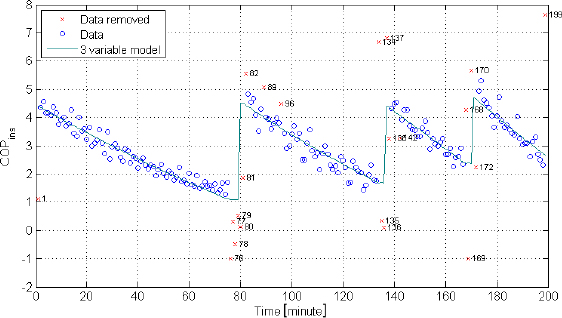
Figure 5 shows the correlation models from US standard test, compared to the measured data, where the correlation models are built from 1 Kelvin interval data. The COPins values predicted by the models are relatively close to the measured values.
COPins predictive from the correlation models compared to COPins measured
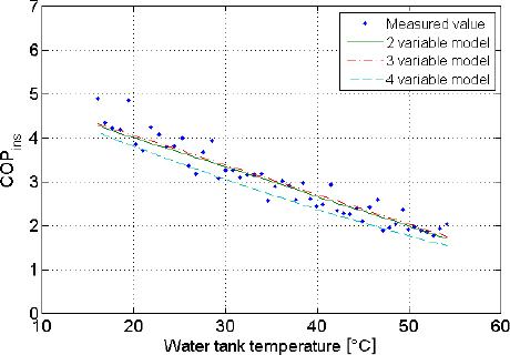
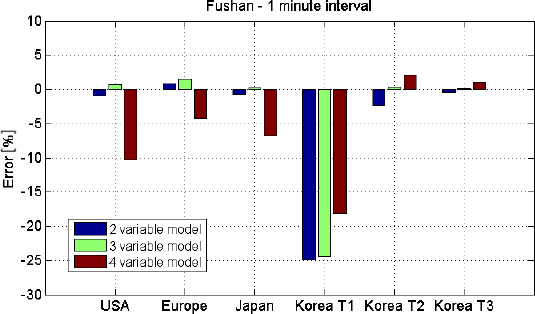
Figure 6 and Figure 7 exhibit graphically the error ε in the 1-Kelvin interval data and 5-Kelvin interval data models. In both cases, the models obtained have reasonable precision for almost all the test standards, except for the Korean test n°1. The main difference between this test and the others relates to the very low inlet water temperature when compared to the water tank temperature. As discussed in part “HPWH simulationfundamentals”, this is because the correlation models are likely to be inaccurate when the tank water temperature differs greatly from the condenser water temperature.
Error in COPint predicted by the correlation models derived from 1-Kelvin interval data compared to experimental measurements
Error in COPint predicted by the correlation models derived from 5- Kelvin interval data compared to experimental measurements
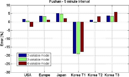
Except for the Korean test n°1, the two-variable and three-variable models have a precision better than 5%. In almost all cases, the four-variable model produces relatively large errors. This may lead to a conclusion that the two-variable and three-variable models are the most appropriate models to be used. Yet the models are all derived from the AS/NZS tests where the air temperatures (dry bulb and wet bulb) are highly correlated. In this case models using both dry and dew point air temperatures may be less accurate as they use redundant data. However, in principle the situation could be reversed in the case of uncorrelated temperature data. In general then, the four-variable model, which is derived from thermodynamic concepts, may give better results.
The models based on 1 Kelvin interval are not always better than those based on 5 Kelvin interval. Indeed, they are better in the Korean test n°3 (errors of about 1% against 5% in the case of the model based on 5 Kelvin interval). However, they are worse in the Japanese test in the case of the 4 variable model.
This section investigates the feasibility of applying the same approach to model a full test that includes a draw-off pattern. In order to do so, the following issues need to be addressed:
Tank heat losses to the environment; while, tank heat losses can be neglected when compared to the heating capacity of the HPWH during a heat-up phase, they need to be accounted for over a longer time period during which the heat losses represent a significant part of the energy balance;
Modelling draw-off cycles requires a time simulation of the tank temperature. Therefore, a COP model depending only on temperature variables is insufficient.
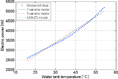
The HP’s heating capacity has to be simulated. This can be done via a supplementary model that gives electricity consumption as a function of temperature variables;
A control-logic model is also required. It should indicate the start and stop times of the HP when operated under a given standard test cycle.
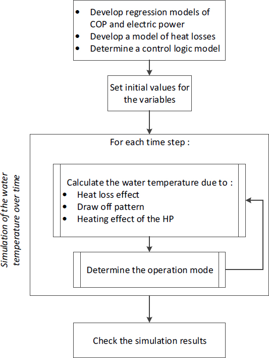
Figure 8 summarises the methodology put forward to model the HPWH operation over a full test cycle including draw-off periods. The following steps are required:
First, regression models of COP and electric power are developed, using experimental test data measured under limited operational conditions (in our study the AS/NZS test cycle). It is also necessary to develop a heat loss model, from the analysis of a cooling-down period. In addition, a control logic model needs to be determined by observing the operation of the HP;
Second, the initial variable values are set in accordance with the specifications of the test standard in question;
The third step is to model the water temperature over time. For each time step, the water temperature is calculated by considering the heat losses, the draw off flow and the HP heating effect. Then, the operational mode of the HP (on or off) is determined;
Finally, the simulation results are checked by comparison with the measured values.
Methodology for modelling HPWH operation over a full test cycle
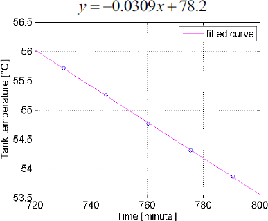
where Tamb is the temperature of the ambient air surrounding the tank and UA is the tank heat loss coefficient. This approach requires a cooling period (i.e. where the HP is stopped and the water tank temperature decreases due to the heat losses), in order to determine the factor UA. In addition, the variation of Tt must be large enough to allow the UA factor to be accurately determined. For these reasons, the following model is used in place of:
where ΔTt is the variation of Tt over a period of time Δt, and the factor Closs can be determined from available test data.
where q is the water flow rate and V is the volume of the tank.
This methodology is applied to the same HPWH considered in previous parts, in order to develop a model such that regression models are derived using four sets of AS/NZS tests. The heat loss model and control model are determined from the analysis of data taken from a test period where the HPWH is in stand-by operation. The performance of the HP is then simulated according to the US test conditions [21] and the predicted results compared to the measured values. Simulation results are subsequently shown.
Evolution of the tank water temperature over time for a cooling phase
Electric power predictive capability of the correlation models
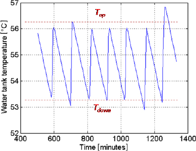
Observations of a period of stand-by operation (shown in Figure 11) indicate that the start/stop of the specific HP is controlled so that the water temperature remains within a narrow temperature band around 55 °C. The control logic is likely to be as follows:
During a heating phase (when the HP operates) the water temperature increases to an upper set-point temperature Tup = 56.3 °C above which the HP stops;
During a cooling phase (when the HP is in stand-by mode) the water temperature decreases until it reaches a lower set-point level Tdown = 53.3 °C under which the HP restarts.
Evolution of the tank water temperature over time during a stand-by period
Predictive capability of the full test cycle model developed under the US test standard conditions
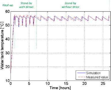
Table 3 compares the simulation results with the measured values. From this it is seen that the heating up time is predicted precisely, with an error as low as 0.6%. The COP error during the heat up phase is small, at about -1%. The temperature loss, defined as the decrease of the tank water temperature due to the heat loss effect and/or the draw-off pattern, has an error of 1.2% over the “stand-by and without draw” period. This indicates that the heat loss model is correct. The error of the temperature loss over the “stand-by with draw” period is higher (-7.5%), probably due to the stratification effect when a drawoff occurs. The COP error in this phase is relatively high (-8.2%), resulting in an error of -6.7% for the whole test.
Comparison of the model simulation results and the measured values for different operational phases (US test standard conditions)
| Simulated | Measured | Error [%] | ||
|---|---|---|---|---|
| Heat up phase | ||||
| Electric consumption | [MJ] | 13.5 | 13.0 | 3.8 |
| Heating up power | [MJ] | 36.6 | 35.6 | 2.7 |
| COP | - | 2.7 | 2.7 | -1.0 |
| Heating up time | [min] | 58.1 | 57.8 | 0.6 |
| “With draw stand-by” phase | ||||
| Electric consumption | [MJ] | 26.5 | 25.5 | 3.7 |
| Energy of the drawn water | [MJ] | 38.0 | 40.0 | -4.8 |
| COP | - | 1.4 | 1.6 | -8.2 |
| Temperature loss | [K] | 43.4 | 47.0 | -7.5 |
| “Without draw stand-by” phase | ||||
| Electric consumption | [MJ] | 16.9 | 15.2 | 11.3 |
| Temperature loss | [K] | 31.9 | 31.6 | 1.2 |
| Whole test | ||||
| Electric consumption | [MJ] | 56.8 | 53.7 | 5.9 |
| Heating energy | [MJ] | 74.7 | 75.6 | -1.3 |
| COP | - | 1.3 | 1.4 | -6.7 |
The results presented above show that it is possible to correctly model a HPWH that only uses a heat pump i.e. that does not also use a back-up electric resistance heater. This section aims to evaluate the feasibility of modelling a heat pump system that includes a back-up electric resistance heater. The experimental test data from a second HPWH are analysed for this purpose.
The following three operational modes are considered:
Periods when only the heat pump is activated;
Periods when only the electric resistance heater is activated;
Periods when both the heat pump and electric resistance are used.
In principle it is necessary to develop a performance correlation model for each of these operational modes. A supplementary model of the control system is also required to be able to predict when each of these modes is operational. This model needs to determine the operational mode as a function of the operating conditions i.e. the air and water temperatures.
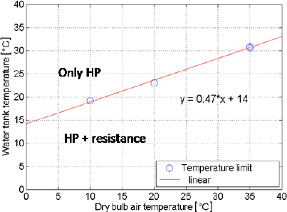
The control logic of the HPWH in question is as follows:
At the beginning of the test period both the HP system and electric resistance heater are used;
When the water tank temperature reaches a specified limit the resistance heater is turned down/off and only the HP works.
Figure 13 shows the water temperature operational-mode limit (i.e. threshold at which the HPWH operates in either the HP-only mode or HP and resistance heater mode) as a function of the dry bulb air temperature, observed from four sets of experimental tests under the AS/NZS standard. From these, the following linear-correlation function (with a coefficient of determination R2 = 0.99) is derived for the threshold tank water temperature Tlim as a function of the dry bulb air temperature Td: Tlim = 0.47 x Td + 14
Temperature limit (thresholds) that separate the two operational modes of the HPWH n°2, as observed from four sets of AS/NZS experimental test data
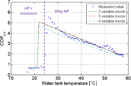
The AS/ZNS test data are also used to develop COP performance correlation models for each operational mode. Three types of models are derived and tested, using two, three and four variables (eq. 8-10). The models obtained are then used to estimate the heat-up phase COP (i.e. without draw off) that would be expected under the Japanese standard test and the estimates are compared to the corresponding test data (Figure 14). It appears that the control model is not completely satisfactory for the Japanese test standard. Indeed, it underestimates the operational mode temperature limit by about 2 K. This error is probably due to the following factors:
The control logic is not exactly determined from the tank water temperature, but from temperature sensors which are imperfectly correlated with the tank water temperature e.g. the condenser water temperature, or the refrigerant temperature;
The control logic may be more complicated than a simple linear model of air and water temperatures.
Predictive capability of the correlation models of the HP n°2 using an electric resistance
The relatively small error in the control correlation model leads to a significant overestimation of the predicted COP compared to the measured COP, with the error ranging from +15 to +22% depending on the model type (Table 4).
The observed error is explicable due to the following considerations:
The HP-resistance heater operational mode only occurs for a short period of time, but nonetheless represents about 50% of the total energy consumption because the design capacity of the resistance heater is much higher than the capacity of the HP;
Inaccuracy in the control model results in a significant underestimation of the length of the HP-resistance operational mode such that the time the resistance heater is working in practice is twice as high as the model estimate.
Despite this the COP correlation models are reasonably accurate during the HP mode, especially for the two-variable model.
Division of the heat-up phase of the Japanese standard test
| Period | Electric consumption measured [MJ] | Heating capacity measured [MJ] | Error of the COP predicted [%] | ||
|---|---|---|---|---|---|
| Model of 2 variables | Model of 3 variables | Model of 4 variables | |||
| HP + resistance | 1.53 | 0.99 | 49.7 | 50.2 | 51.0 |
| Only HP | 1.52 | 4.52 | 0.0 | 1.3 | -8.6 |
| Total | 3.05 | 5.51 | 21.2 | 22.4 | 15.1 |
In principle COPins depends on the water temperature surrounding the condenser. Depending on the specific configuration of the HP under consideration, the water temperature surrounding the condenser may be the temperature of the inlet water, the temperature of the outlet water, or even a combination of the two. Due to a lack of appropriate experimental test data, it has been necessary to use the average tank water temperature as the correlating variable for the current study. This is likely to be an appropriate choice when the water being supplied to the condenser is drawn from the water storage tank and the water in the latter is well mixed i.e. is not stratified; and these conditions are more or less satisfied in almost all of the experimental tests investigated in this study. However, it is important to recognise that a model based on average tank water temperature is unlikely to produce reliable results for the following situations:
When the water supplied to the condenser is drawn directly from the mains water supply (but not from the storage tank), which is true for the Korean tests. In this case, significant error could occur when the inlet water temperature differs appreciably from the tank water temperature, as occurs in Korean test n°1;
When tank stratification occurs. In the tests studied, this phenomenon is observed in the case of the second HP and only at the beginning of the test (probably due to the activation of the electric resistance heater). The lack of information regarding the exact configuration of the HPWH (i.e. of the geometry of the condenser coil and location of the resistance heater in the tank) and of the inlet and outlet water temperatures does not permit an in-depth study of the impact of this phenomenon on the predictive capability of the model developed.
To avoid these problems, the tank water temperature used in the correlation model should be replaced by a more appropriate variable, depending on the specific configuration of the HPWH.
Due to the lack of appropriate test data, the heat loss model is reduced to a simpler form which is only appropriate in specific conditions (ambient air temperature constant, little variation of the tank water temperature). In order to generalize the methodology for other conditions, a heat loss model based on (eq. 12) would need to be developed.
In addition, the proposed methodology considers that the control logic is the same in all operational modes (heat up, stand-by with or without draw-offs). While this is relatively true for the HPWHs studied, the method may not be appropriate for a HP that uses different control logic dependent on the operational mode. For example, the case when full-load control is used in the heat-up phase and part-load control in the stand-by phase. Additional information on the control system (frequency control, cyclic operation control) used by the specific model of HPWH would then be required to simulate the overall COP. This appears to be a particularly difficult challenge due to the range of differing part load circuitry and control logic used by different manufacturers and it seems unlikely the control logic could be deduced from experimental data. Thus, this limitation could only be overcome if information about the part load circuitry and control logic were to be made available by the manufacturer. In principle, the provision of such information could enable the development of performance models allowing reliable performance prediction over a full test cycle including draw-off patterns.
This paper examined the potential to model HPWH energy performance. A simulation methodology applicable to the heat-up phase was presented wherein models of instantaneous COP were developed using regression techniques. The average COP performance for a standard test was then calculated and compared to the measured values. Three correlation models based on two, three or four-variables were examined.
This method was tested for four sets of AS/NZS standard test data for a HPWH. The performance models obtained were then used to estimate the COP that would be expected when the same water heaters are tested in accordance with other international standard test procedures and the estimates are compared to experimental data measured for the water heaters tested under these other standards; specifically the heat-up phases of the US, Japanese and European test standards and the steady-state Korean test standard. The simulation results produced are in close agreement with the measured data.
The method was also used to simulate performance over a full test cycle including a draw off pattern. This required an electric power model and a heat loss model to be developed In addition to the COP model. These models allowed evolution of tank water temperature over time to be determined. The resulting simulations had acceptable errors when compared to the measured values.
It can therefore be concluded that the models developed from the AS/NZS tests give accurate predictions of the HPWH COP during the heat-up phases under other international test standards, and thus could be used to avoid the need to carry out additional physical tests for those standards.
The two-variable and three-variable models give the best results on average, compared to the four-variable model, which is due to the dry bulb and dew point air temperatures used to derive the models being highly correlated.
The limitations of the methodology proposed were also discussed, specifically regarding; the difficulty in modelling a hybrid system (heat pump + electric resistance heater), the choice of regression variables used in the model and the potential to model COP performance over a full test cycle including a water draw-off pattern. Recommendations were also given to improve the methodology.
| cp | heat capacity | [J/kg °C] |
| m | water mass | [kg] |
| heating power | [W] | |
| T | temperature | [°C] |
| electric power | [W] | |
| ε | error | [%] |
| t | time | [s] |
| a | air |
| d | dry-bulb |
| dew | dew point |
| f | final moment |
| i | initial moment |
| ins | instantaneous value |
| int | integrated value |
| t | tank |
| w | water |
| AS/NZS | Australian/New Zealand Standard |
| COP | Coefficient of Performance |
| HP | Heat Pump |
| HPWH | Heat Pump Water Heater |
This work was supported by a Grant (project Heat pump water heaters) from APEC Expert Group on Energy Efficiency and Conservation. The authors wish to thank Dr. George Wilkenfeld and his experts for their very helpful comments on the work. A special thanks is also given to the Korea Testing Laboratory who collected the data that the present study used.
- ,
Potential of Demand Side Management to Reduce Carbon Dioxide Emissions Associated with the Operation of Heat Pumps ,J. Sustain. Dev. Energy, Water Environ. Syst , Vol. Vol. 1 (No. 2), :94-1082013, https://doi.org/10.13044/j.sdewes.2013.01.0007, pp - ,
Reversible Heat Pump Model for Seasonal Performance Optimization ,Energy Build , Vol. Vol. 42 (No. 12), :2269-22802010, https://doi.org/10.1016/j.enbuild.2010.07.007, pp - ,
Energy Consumption Modeling of Air Source Electric Heat Pump Water Heaters ,Appl. Therm. Eng , Vol. Vol. 30 (No. 13), :1769-17742010, https://doi.org/10.1016/j.applthermaleng.2010.04.008, pp - ,
Mathematical Modeling and Simulation Application to Visualize the Performance of Retrofit Heat Pump Water Heater Under First Hour Heating Rating ,Renew. Energy , Vol. Vol. 72 , :203-2112014, https://doi.org/10.1016/j.renene.2014.07.011, pp - ,
Modelling and Simulation of a Heat Pump for Simultaneous Heating and Cooling ,Build. Simul , Vol. Vol. 5 (No. 3), :219-2322012, https://doi.org/10.1007/s12273-012-0089-0, pp - ,
A semi-empirical Modeling Study on the Defrosting Performance for an Air Source Heat Pump Unit with Local Drainage of Melted Frost from its Three-circuit Outdoor Coil ,Appl. Energy , Vol. Vol. 136 , :537-5472014, https://doi.org/10.1016/j.apenergy.2014.09.012, pp - ,
Performance Modeling of Air Cycle Heat Pump Water Heater in Cold Climate ,Renew. Energy , 2015, https://doi.org/10.1016/j.renene.2015.08.055 - ,
Quasi-Steady State Modeling of an Air Source Heat Pump Water Heater,” ,Energy Procedia , Vol. Vol. 6 , :325-3302011, https://doi.org/10.1016/j.egypro.2011.05.037, pp - ,
Dynamic Model and Experimental Study of an Air–water Heat Pump for Residential use ,Int. J. Refrig , Vol. Vol. 36 (No. 3), :674-6882013, https://doi.org/10.1016/j.ijrefrig.2012.11.006, pp - ,
Air Source Heat Pump Water Heater: Dynamic Modeling, Optimal Energy Management and MiniTubes Condensers ,Energy , Vol. Vol. 64 , :1102-11162014, https://doi.org/10.1016/j.energy.2013.11.017, pp - ,
Annual Performances of Reversible Air-to-water Heat Pumps in Small Residential Buildings ,Energy Build , Vol. Vol. 65 , :299-3092013, https://doi.org/10.1016/j.enbuild.2013.06.016, pp - ,
Seasonal Performance Evaluation of Electric Air-to-water Heat Pump Systems ,Appl. Therm. Eng , 2015, https://doi.org/10.1016/j.applthermaleng.2015.03.026 - ,
Recent Developments in Simulation Techniques for Vapour-compression Refrigeration Systems ,Int. J. Refrig , Vol. Vol. 30 (No. 7), :1119-11332007, https://doi.org/10.1016/j.ijrefrig.2007.02.001, pp - ,
Modeling of End-use Energy Consumption in the Residential Sector: A Review of Modeling Techniques ,Renew. Sustain. Energy Rev , Vol. Vol. 13 (No. 8), :1819-18352009, https://doi.org/10.1016/j.rser.2008.09.033, pp - ,
A Review for Numerical Simulation of Vapor Compression Systems ,in International Refrigeration and Air Conditioning Conference , 2010 - ,
Applications of Artificial Neural Networks for Refrigeration, Air-conditioning and Heat Pump Systems-A Review ,Renew. Sustain. Energy Rev , Vol. Vol. 16 (No. 2), :1340-13582012, https://doi.org/10.1016/j.rser.2011.10.015, pp - ,
Fuzzy Multivariable Control of Domestic Heat Pumps ,Appl. Therm. Eng , Vol. Vol. 90 , :957-9692015, https://doi.org/10.1016/j.applthermaleng.2015.07.068, pp - ,
Seasonal Performance Rating of Heat Pump Water Heaters ,Sol. Energy , Vol. Vol. 76 , :147-1522004, https://doi.org/10.1016/j.solener.2003.08.007, pp - ,
Australian / New Zealand Standard 5125.1, Heat Pump Water Heaters — Performance Assessment Part 1: Air Source Heat Pump Water Heaters , 2010 - ,
The Reference to EnergyPlus Calculations , 2012 - ,
Code of Federal Regulations (CFR) Title 10, Part 430, Subpart B Appendix E, Uniform Test Method of Measuring the Energy Consumption of Water Heaters , 2012 - ,
EN 16147, Heat Pumps with Electrically Driven Compressors - Testing and Requirements for Marking of Domestic Hot Water Units , 2011 - ,
JIS C 9220, Residential Heat Pump Water Heaters , 2011 - ,
Air Source Heat Pump Water Heater for Residential Buildings (In draft – not yet published) , 2013