


Global warming and climate change are among the major challenges the world is confronting. Induced by increased levels of greenhouse gases emissions in the atmosphere, many industries are yet to consider adequate and more efficient solutions to tackle their industrial processes and their CO2 emissions. Figure 1 illustrates the CO2 emissions of the most energy intensive industries in the world, where iron and steel industry being the biggest contributor [1]. The emissions are manly attributed to the enhanced greenhouse effect that results from the higher levels of the trapped heat radiation through the increasing atmospheric concentration of gases like CO2 [2].
Global industries direct CO2 emissions in the sustainable development scenario, 2000-2030 [1]
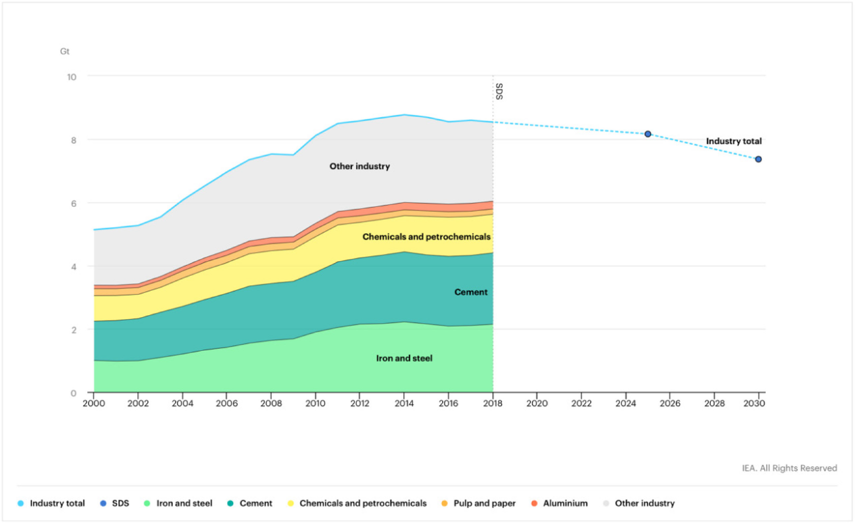
Research shows that CO2-caused global warming in the long term is 25 times stronger than its immediate effects, and it is responsible for approximately 92% of the heat-up that is caused by production in iron, steel, and electricity generation industries [3]. In 2018, every ton of steel produced around the world emitted on average approximately 1.85 tons of CO2 in the atmosphere, which equates to about eight percent of the overall global CO2 emissions [4].
As countries seek ratifying the Paris Agreement, many have set the combat against climate change as a priority. In its recent Energy Efficiency Directive, the European Council has endorsed a target of 30% energy savings by 2030 for Europe energy use, including sectors such as electric generation and industries [5]
Heavy industries such as the steel industry are highly affected by such strategies and must, therefore, make operational changes accordingly. Industries must adopt strategic changes which include early planning for technology and process changes, as well as the restructuring of current production routes to meet energy and emission requirements. One prominent method in steel manufacturing, which we explore further in this study, is through energy optimization and exploring options for waste heat recovery.
Heat recovery potential in the steel industry has been investigated since many years. It represents a great opportunity to reduce the consumption of primary energy while increasing the competitiveness and sustainability of the steel industry. More specifically, in steel plants where the manufacturing process uses the electric arc furnace (EAF), which account for about 28% of the worldwide steel production [6], the waste heat is estimated to get up to one-third of the total energy supplied to the process [7]. Heat recovery technologies have been developed for waste heat recovery in EAF. They have been classified based on the adopted heat recovery approach, which can be direct, indirect, or innovative. P. Nardin et al. [8] have proposed a complete classification of current technologies for waste heat recovery from EAF.
The list of technologies is presented in Table 1. Every recovery approach in the first column has at least two sub-categories or methods of implementation in the second column. Upon investing in a WHR process, it is essential to consider all potential gains and evaluate the profitability of such investment. Hence, the last column is divided into two options for utilizing the recovered energy, either internally to feed back into the process or sold externally.
Current technologies for waste heat recovery from EAF [8]
| Recovery Approach | Sub-category | User | |
|---|---|---|---|
| Internal | External | ||
| Direct | Continuous charge | Scrap preheating | - |
| Discontinuous charge | Scrap preheating | - | |
| Indirect | Steam | Internal processes | Industrial symbiosis |
| - | District heating | ||
| Power generation |
Electricity grid | ||
| Hot water | Power generation |
Electricity grid | |
| - | District heating | ||
| Innovative | Phase Change Material (PCM) based devices | Power generation |
Electricity grid |
| Concrete | Power generation |
Electricity grid | |
| Molten salt | Power generation |
Electricity grid | |
One characteristic of the source of heat in the case of the EAF process is that it is fluctuating and intermittent, which represents barriers to the implementation of ORC for the waste heat recovery [9]. This major constraint in the implementation of WHR is due to the fluctuation and intermittence of the heat flows that happen in industrial processes [10]. Indeed the waste heat recovery systems are designed to operate at a design point that usually corresponds to maximum thermal power available at the waste heat source [11]. This problem has been investigated extensively by several authors. M. Jimenez-Arreola et al. [12] have proposed an overview of most of the solutions that have been developed to address this issue. Most of the solutions proposed to manage the fluctuations and intermittence of waste heat power are using either Steam Rankine Cycle (SRC) or Organic Rankine Cycle (ORC) for the recovery of the waste heat energy. Furthermore, WHR systems could be classified into two main categories, Steam Control and Thermal Energy Storage.
The Steam Control method doesn't require thermal energy buffer to manage the heat fluctuations. It uses valves to reduce mass heat stream fluctuations [13]. The technical options to manage the fluctuations using Steam Control method include Heat source by-pass, Heat source dilution, and Working with fluid flow control [12].
Thermal Energy Storage has been developed and used more efficiently in handling the fluctuations of thermal energy. The technical options of TES are based on either Sensible Heat Storage (SHS), or Latent Heat Storage (LHS) [14]. SHS options include hot water tanks, and molten salts, while LHS technical options include steam accumulators and Phase Change Materials (PCMs) [15]. PCMs most commonly used are paraffin, salt hydrates, and fatty acids [16]. LHS with PCMs applications have been developed as buffer in the thermal power fluctuations in the EAF off-gases [17], [18].
The inventory of the current principal solutions for the mitigation of the heat fluctuations in waste heat recovery systems has been completed by [12] and is shown in Figure 2.
Principal solutions to manage waste heat thermal power fluctuation [12]
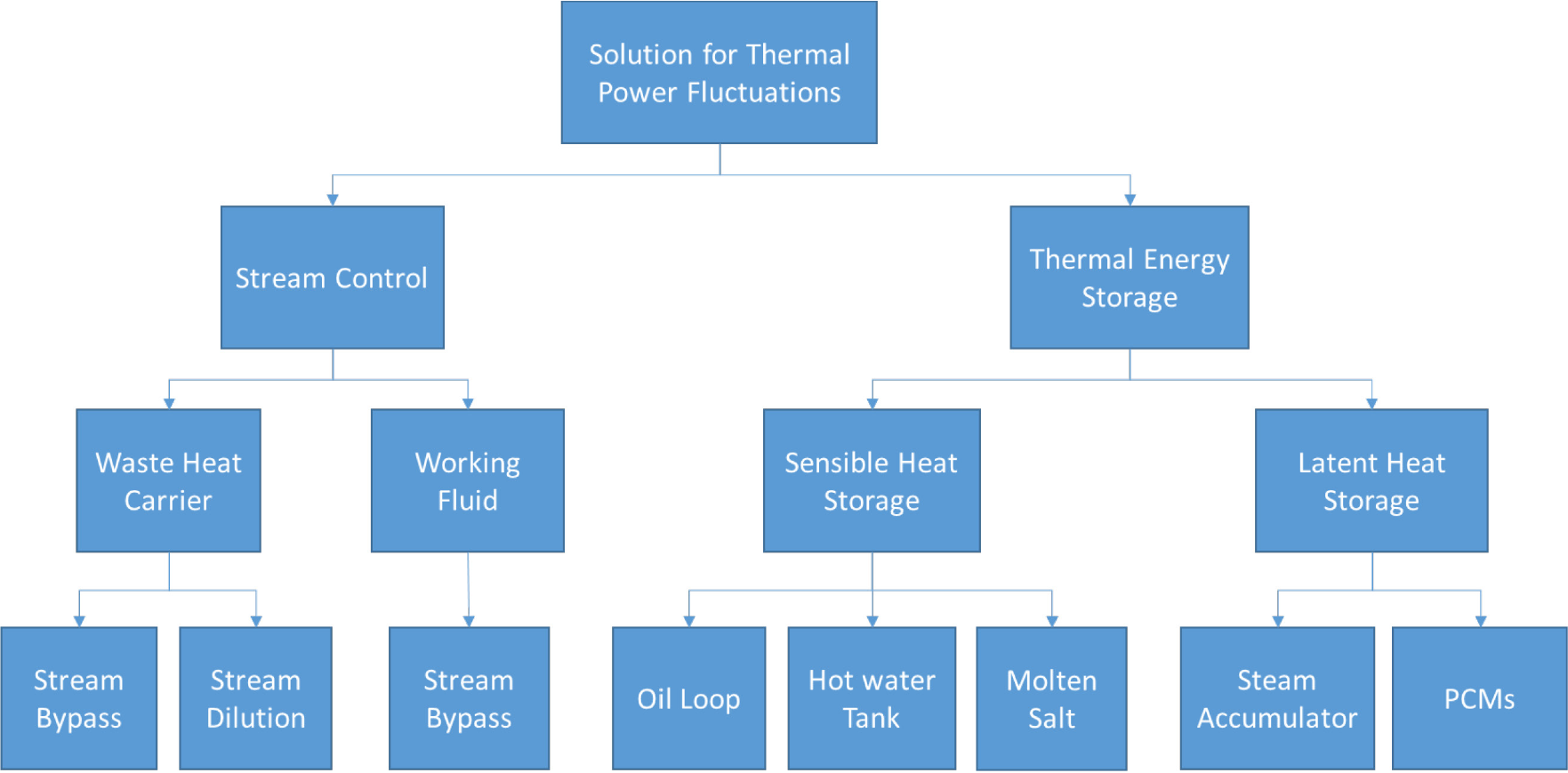
M. Jimenez-Arreola et al. [12] have also conducted a comprehensive assessment of the technical options to manage the thermal power fluctuations. The main finding of this assessment is that TES, including both LHS and SHS, provides the most efficient solution with regards to the fluctuation removal and the efficient energy use potential.
Among the innovative technologies, thermal energy storage mediums like Concrete blocks and molten salts as heat transfer and storage media have shown promising performances. An experimental plant was developed by Siemens Metals Technologies in an electric steel plant in Germany in 2012. The objectives of this pilot project were to investigate the possible materials to use in the heat recovery system, and the conditions required to achieve the highest energy recovery efficiency. The results of the research were presented by [19], and showed promising findings. With a tapping weight of 120 tons, the energy in the off-gas is around 370 kWh per ton of liquid steel, up to 24 percent of this energy can be recovered and used to generate electricity.
However, the overview of WHR technology options proposed by [12] didn't include the Concrete TES solution among the solutions investigated. Indeed, as reported by [8], it is classified among the most innovative waste heat recovery approaches. In this study we propose to investigate the potential of Concrete TES solution to manage the fluctuations of the thermal energy waste in the off-gases of the EAF.
In our study, we propose to investigate the use of High Temperature Concrete as a means for heat transfer and storage, and to estimate the heat recovery potential in an EAF steel manufacturing plant. We present an assessment of a steel manufacturing process, and demonstrates the potential of thermal energy storage systems (TES) in recovering heat from the high-temperature exhaust fumes of the EAF. Our investigation entails mapping the material and energy requirements of one phase of the current steel production method, i.e., natural gas reforming for syngas production; direct reduction of the iron ore; and secondary refining to obtain the steel in the electric arc furnace. Further, we design an energy storage system using concrete and a heat transfer fluid (HTF) to recover the waste heat generated by the EAF through an ORC, and to evaluate the overall energy efficiency improvement of the process.
The course of actions followed in this research project is presented in the flow-diagram in Figure 3 below, and will be applied to a case study of a steel manufacturing plant using the Direct Reduction – Electric Arc Furnace (DR-EAF) based process.
Proposed method plan steps
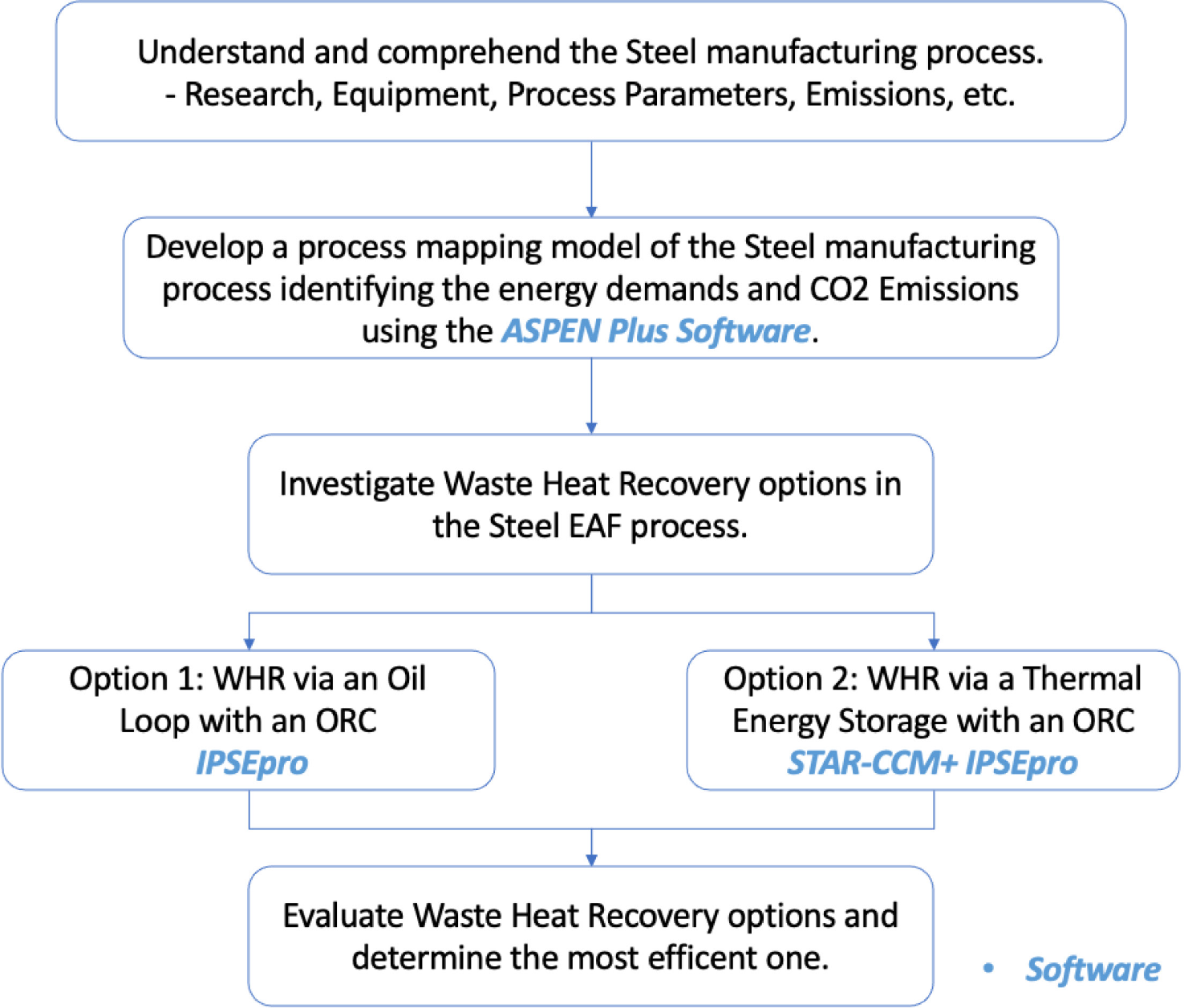
To illustrate the implementation of the proposed method of investigation, we propose to use a case study. We begin by presenting the studied steel manufacturing plant, then we present the process mapping model developed with Aspen software, and finally we investigate the WHR potential using an ORC with and without TES means.
The steel manufacturing route at the plant of study implements the Direct Reduction – Electric Arc Furnace (DR-EAF) route. The plant imports the iron ore pellets and processes them to manufacture a wide range of products including reinforcing bars, wire rods, steel billets, and heavy sections. The plant was commissioned in 2 phases with each producing about 1.6 million tons/year of directly reduced iron (DRI) and about 1.4 million tons/year of steel. Both phases use an external reformer to produce synthesis gas (CO and H2) which is fed to the direct reduction shaft for reducing the iron ore into sponge iron. This is followed by secondary steelmaking in the EAF and ladle furnaces. The DRI technology utilized at the steel plant under study is ENERGIRON III, which is the product of a collaboration between the two companies, Tenova and Danieli. Tenova, headquartered in Italy, is a worldwide partner for sustainable, innovative, and reliable solutions in metals and mining industries, whereas Danieli is an Italian supplier for equipment and physical plants to the global metal industry. This technology features an external steam reformer which is placed off-line from the process gas recirculation circuit for the following reasons [19]:
The reformer catalyst is not affected by contaminants coming from the pellets (sulfur and other poisons);
The reformer catalyst is not affected by upset conditions in the process gas, such as the CO2 and CH4 content.
ENERGIRON III direct reduction process and HYTEMP system [19]
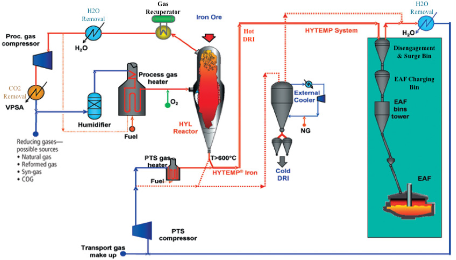
The synthesis gas from the external reformer unit is first passed through an industrial humidifier that maintains it under specific humidity level preventing any static electricity build-ups and preserving its properties. After that, the synthesis gas is heated to reduction temperatures, using a fired heater, and then fed into the shaft furnace. The exhaust gas (top gas) leaves the furnace and passes through a top gas recuperator for heat recovery, followed by an H2O removal stage where H2O is separated and removed from the top gas, it can later be used to feed the fired heater. The top gas is then compressed and fed into a Vacuum Pressure Swing Adsorption (VPSA) process where CO2 is removed, and the top gas is finally recycled back. Hot DRI (HDRI) exiting the furnace is delivered to the HYTEMP system, developed by Tenova's HYL technologies.
This process uses nitrogen as the transport gas, and utilizes pressure build up rather than velocity of the gas for the transport process. This is to avoid degradation of the DRI. When the HDRI reaches the EAF bins tower, the gas is separated and recycled back into the process.
Table 2 summarizes the operating parameters of the ENERGIRON direct reduction process and Table 3 contains the chemical analysis of DRI produced at the respective plant. Both these tables are used to validate the results of the simulation model produced.
Operating parameters of the ENERGIRON direct reduction process
| DRI Process parameters | Value |
|---|---|
| DRI yearly capacity in tons (t/y) | 1,600,000 |
| Iron ore / DRI (t/t) | < 1.4 |
| Metallization (%) | > 94 |
| Carbon content (%) - *Up to 60% as Fe3C | 1.5-3.2 |
| Natural Gas Consumption per ton of DRI (Gcal/t) | 2.65 |
| Electrical Energy Consumption per ton of DRI (kWh/t) | < 30 |
| DR Process yearly hours of continuous operation (h) | 7560 |
Chemical analysis of DRI produced at plant of study
| Chemical Analysis | Range % |
|---|---|
| Iron (Fe Total) | 91.5-92 |
| Iron (Fe metallic) | 86-88 |
| Metallization | 94-95.5 |
| Silicon Dioxide (SiO2) | 1.7-2 |
| Aluminum Oxide (Al2O3) | 0.6-0.8 |
| Calcium Oxide (CaO) | 0.8-0.9 |
| Magnesium Oxide (MgO) | 0.1-0.4 |
| Carbon | 2.2-2.5 |
| Sulphur (S) | 0.007-0.01 |
| Phosphorus (P) | 0.04-0.05 |
The EAF technology employed at the plant of study is a DANARC module (manufactured by Danieli) with a 150-tons capacity and an average tap-to-tap (TTT) time of 46 min per batch of HDRI. It is mounted with 5 oxygen and 3 carbon injectors. The EAF is also mounted with a cooling unit to maintain the structure and refractories within safe operating limits. This is done using water circulated through pipes that form a panel. Table 4 summarizes the operating parameters of the EAF under study.
EAF operating parameters
| EAF Process Parameter | Value |
|---|---|
| Capacity (t) | 150 |
| Tap-to-tap time (min) | 38-52 (depending on hold/cold DRI proportion) |
| Oxygen injectors (m3/h) | 30 (each) |
| Carbon injectors (kg/min) | 2200 (each) |
| EAF Type | AC, split shell, EBT system, conductive arm, DANARC module |
| Electrical Energy Consumption per ton of liquid steel (kWh/t) | 380-520 (depending on hot / cold DRI proportion) |
| Steel making plant capacity (t/y) | 1,400,000 |
Given the batch nature of electric arc furnaces and their fluctuating gases, energy storage systems are required to output a continuous flow of thermal energy. A commonly considered approach for storing sensible heat is the use of solids [20], and High Temperature Concrete is consequently a viable alternative. The solid storage medium would have a number of pipes allowing heat transfer in between itself and the heat transfer fluid passing through. However, the creeping of concrete need to be taken into account as it results in slits in between the oil pipes and the concrete block that will degenerate the heat conduction. Although such issues are out of the scope of this current study, they are to be considered in future extensions of this work.
The second step of the proposed method is related to the process mapping. In this section, we present the mapping of the studied manufacturing plant, its equipment, requirements, processes parameters and its GHG emissions to get a more comprehensive understanding of the steel manufacturing processes.
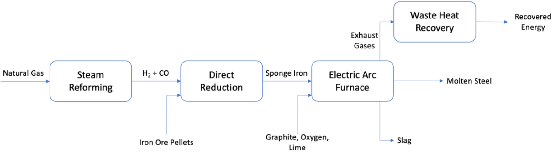
The following schematic presented in Figure 5 gives a high-level overview of the plant studied.
Overview of plant studied
This framework is then integrated into an ASPEN Plus model to simulate the flows in a steady state simulation. The results of the simulation help us identify the most energy intensive process. Simulation-based investigations would take place to evaluate the amount of energy that can be recovered by fully utilizing the waste heat exhausted by the EAF.
To achieve the set-out objectives of this study, we first simulate the DR-EAF steel-making route in the steady-state process simulation software, Aspen Plus ® V10. For a given process design and with an appropriate selection of thermodynamic models, Aspen Plus uses mathematical models to predict the performance of the process. This simulation is carried out to consolidate the mass and energy flow of the manufacturing process, and helps in identifying ways to improve its energy efficiency. Simulation of the existing plant includes the following major sub-processes: steam reforming of natural gas to produce synthesis gas (H2 and CO), direct reduction for the reduction of iron ore pellets, and secondary steelmaking in the electric arc furnace (EAF). This analysis has helped in identifying the EAF as the most energy intensive.
Using a prior, built-in model [21] for steam reforming as a basis, we increase the capacity to produce enough synthesis gas for the scale of the steelmaking facility and expand further on the model to incorporate the remaining subsystems of the plant. To simulate the performance of the process, Aspen Plus requires inputs such as a list of all components taking place in the system, features of inlet streams (e.g. Composition, temperature, pressure, and flowrates), chemical reactions taking place, and appropriate unit models. The outputs are the characteristics of intermediate and final flows, such as chemical compositions of sponge iron, molten steel, slag etc., together with the energy consumption and calculated operating conditions of temperature and pressure resulting from the process. Figure 6 illustrates the process model developed. A step-to-step explanation of every process within the developed model of the plant studied is disclosed in the sections following Figure 6.
ASPEN process model
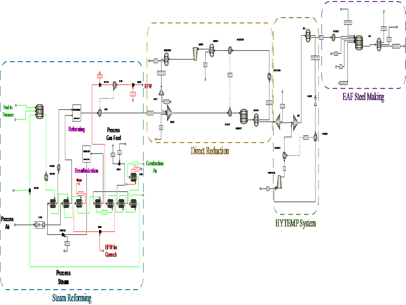
The model developed helped to understand, trace and further comprehend the flows and comportments of the individual processes within the considered plant. Nevertheless, as there was a lack of actual data from the field, being able to have a reference frame was an absolute necessity. Hence, the main objective of developing such a model was to monitor both, the high energy consumption and process related emissions of each stage and cross reference them with the literature and resources used in further steps. Having this model as a reference assured that all values taken from literature are consistent and in line with what is expected.
The next sections present the description of each step in the manufacturing process of the studied plant, and as presented in Figure 5.
The external reformer section is driven by the combustion of natural gas fed as fuel. The released energy is supplied to other units via a heat exchanger network. The natural gas (Process Gas Feed) is delivered as dry gas containing about 40 ppm by weight of sulfur, which is a poison for the reformer's nickel-based catalyst. The desulfurization unit reduces the sulfur content to about 5 ppm by hydrogenating it to hydrocarbons and hydrogen sulfide and then absorbing the hydrogen sulfide in zinc oxides. The reforming unit contains two sections, primary reforming and secondary reforming. The desulfurized hydrocarbon feed is reformed to hydrogen and carbon oxides in the presence of steam in the primary reformer, and additionally with hot air in the secondary reformer.
The main reaction occurring in the reformer is the endothermic conversion of methane to synthesis gas (CO and H2):
(1)
The reformed gas is directed to the direct reduction section where it joins the purified recycled gas coming from the direct reduction shaft. This resulting gas is heated up to the operating shaft temperature of 700 °C in the process gas heater and directed into the shaft where it circulates upwards in counter-current direction with the iron ore pellets moving downwards by gravity.
The reactions taking place in the shaft are as follows:
(2)
(3)
(4)
(5)
(6)
(7)
Carburization reactions:
(8)
(9)
(10)
The top gas leaving the reactor contains H2O and CO2 produced by the reduction reactions and carries considerable sensible heat. As such, the thermal energy in the top gas is first recovered in a recuperator (gas-gas heat exchanger) and is used to preheat the feed gas going into the shaft. Downstream the recuperator, the top gas passes through a scrubbing system for dust removal and a quenching system for cooling and removal of water. The treated gas is then compressed and sent to an absorber for selective CO2 removal through direct contact with an amine-based liquid solution. A small part of the gas leaving the absorber is purged out of the system to prevent the build-up of impurities in the system, whilst the remained is recycled back and mixed with the synthesis gas, thus closing the process loop.
The sponge iron (DRI) produced is at around 700 °C (HDRI). Due to the limited capacity of the electric arc furnace (150 tons), some of the produced DRI is externally cooled and stored as cold DRI (CDRI) until the melt shop is ready to use it. The external cooling vessel was not accounted for in this study but will be in future extensions of this work. HDRI produced is directly transported to the electric arc furnace through the HYTEMP system. When the HDRI reaches the EAF, the gas is separated, quenched, and compressed. Make-up gas is added to the stream to compensate for the losses before it is heated and recycled. During the separation, the pressure of the HDRI is brought to atmospheric pressure to be fed into the EAF by gravity.
Once the HDRI is fed into the EAF, the roof is lowered, and the electrodes submerged for arc application which commences the melting portion of the cycle. As this is an AC furnace, hold and cold spots exist around the hearth perimeter and between electrodes. As such, oxygen-fuel burners in the sidewall of the furnace provide chemical energy to the cold-spots, making the heating of the steel more uniform. Additional chemical energy is provided by injecting oxygen and carbon into the furnace. The lime is added to remove impurities and form a foamy slag that can be separated from the steel and poured out from the furnace as a liquid. The steady-state simulation of the process model helped in identifying the EAF as the most energy intensive and CO2 emitting activity within the process. The study therefore focuses on the EAF and the ways to improve its energy efficiency by developing an applicable WHR model.
The third step of the proposed method is related to the investigation of WHR techniques that could be implement at the EAF process. Two WHR models were selected and their simulations were developed to evaluate their performance. The two scenario models are: an Oil Loop with an Organic Rankine Cycle (ORC), and a Thermal Energy Storage (TES) made of a concrete block with an ORC. Unlike the conventional water-steam power generation cycles, power plants that are based on ORC technology are less demanding in terms of auxiliaries, safety systems, maintenance and operating costs [22]. The models are simulated using two software: SimTech's IPSEpro and Siemens's STAR-CCM+.
Due to the unavailability of actual data from the field of the considered plant, the input signals were based on the off-gas temperature and flow rate profiles from a similar EAF and presented in Figure 7 [23].
The reference cycle [23]
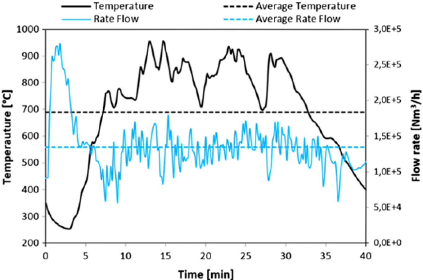
The EAF used here has a production capacity of 80-90 tons per TTT cycle. Although this EAF is relatively lesser in term of its capacity to the one installed in the studied plant, its average TTT time, mass flow and temperature are comparable to the 150 tons EAF considered.
The initial states were disregarded in order to avoid any irregularities and the considerations were set to include the profiles from t = 5.4 min onwards. This was acknowledged as the reference cycle to be considered in the characterization of the waste heat recovery process.
The first WHR model was simulated using IPSEpro, a software system for calculating heat balances and simulating processes. Since Aspen Plus only simulates in steady-state, IPSEpro was used to get a more comprehensive idea of the transient influence on the suggested model and gain a deeper understanding of the dynamic responses of its processes.
Figure 8 below illustrates the process model for an intermediate oil loop that according to [24] would be able to convert the exhaust heat fluctuations in temperature into fluctuations in mass flow rate. This is achievable by maintaining the oil temperature as constant while controlling its mass flow rate [24]. The heated oil then moves into the Organic Rankine Cycle (ORC) evaporator heat exchanger in order to help evaporate its working fluid. The oil used as a heat transfer fluid is Therminol VP-1, an ultrahigh-temperature vapor/liquid phase fluid that has been extensively researched and particularly recommended for such purposes [24].
IPSEpro waste heat recovery Model 1
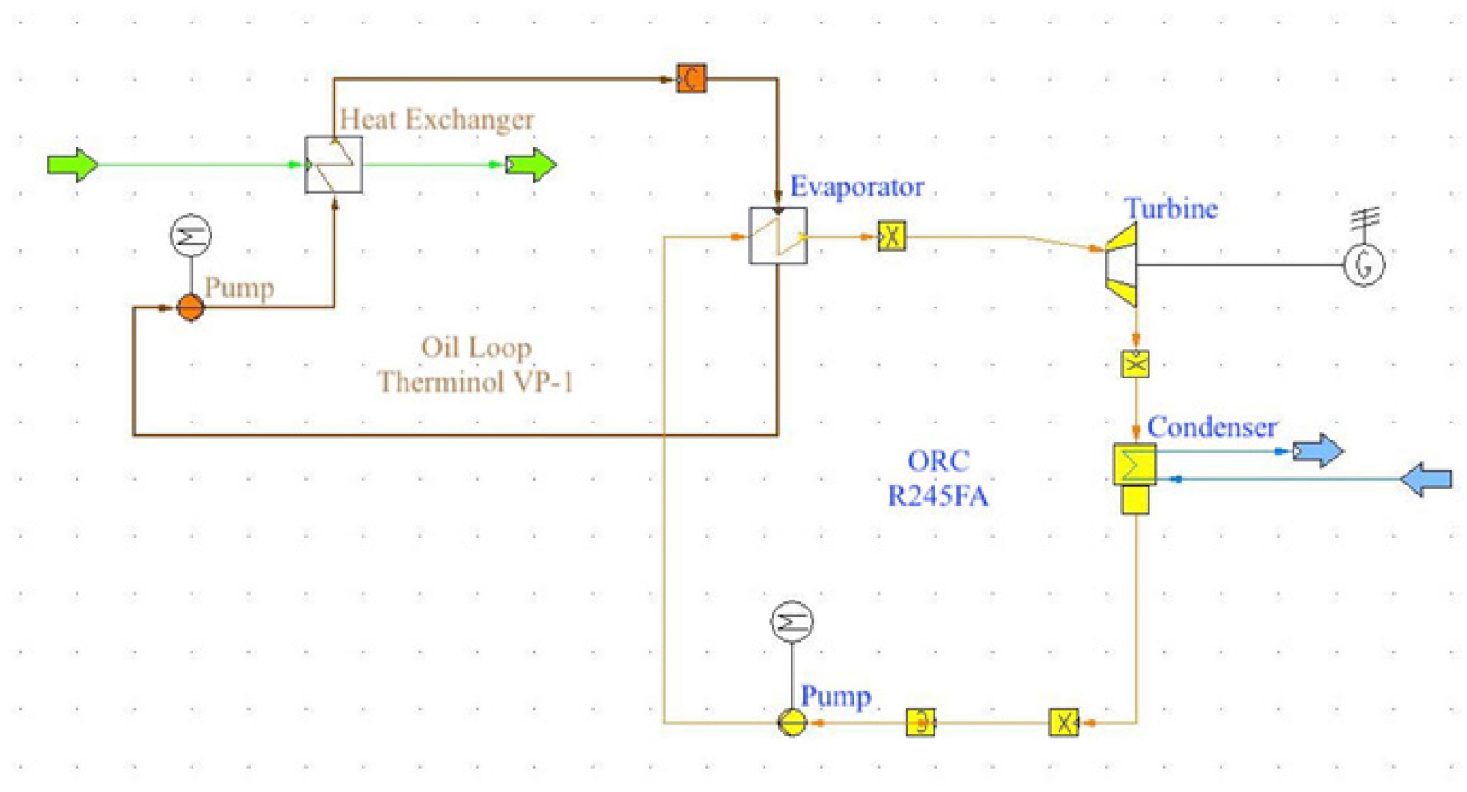
ORC are recommended as a valued technology for waste heat recovery at low and medium temperatures, to the purpose of producing electricity in some cases or combined heat and power (CHP) in others [24]. An ORC is made of four key components: an evaporator, where its working fluid is vaporized; a turbine, where the subsequent thermal energy of the fluid is converted into power; a condenser, where the fluid is condensed back into its initial liquid state; and a pump, where the condensed fluid is impulse to the high evaporation pressure [24]. There has been plentiful of organic fluids that could be used to operate an ORC. However, choosing the appropriate working fluid for a particular WHR application depends on several factors including heat source characteristics, performance, environmental, operational, and economic aspects which has been discussed extensively in the literature. Several studies concluded that the optimal selection of an organic fluid is based on a correlation between the heat source and the critical temperature of the working fluid [25]–[29]. In this study, several fluids have been examined from the literature including R245fa, R245ca, R236ea, Cyclohexane, Cyclopentane, Isopentane, and Toluene considering the operational constraints such as maintaining a minimum pinch temperature of 10 °C, cooling water outlet temperature, and turbine inlet vapor quality of 1.
The second WHR model was also simulated using IPSEpro. However, the Thermal Energy Storage medium was first simulated in STAR-CCM+, a commercial Computational Fluid Dynamic (CFD) based simulation software, extensively used for the simulation of products operating under real-world conditions. However, in order to smoothen the electrical power output profile and get a more stable source of electricity, the gas/oil heat exchanger shown in Figure 8 is replaced with the Concrete Thermal Energy Storage (TES) block seen in Figure 9. It is stated in [30], that utilizing thermal storage units is essential when dealing with intermittent heat production technologies. In addition, and according to [31], the implementation of High Temperature Concrete as a storage medium has demonstrated less environmental impact, even though other TES alternatives such as Molten Salts and Phase Change Materials (PCM) have had a higher value of embodied energy. Furthermore, the cost of the TES material is directly proportional to the intricacy of its fabrication procedure and although this is beyond the scope of this study, it is worth stating that High Temperature concrete or ceramic is significantly less expensive in terms of the cost per ton than the other materials [31].
Geometry scene of the sensible TES block [32]
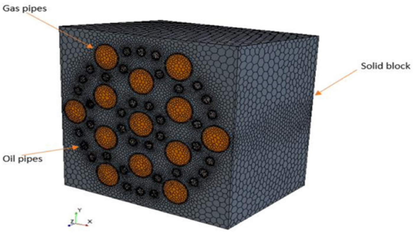
The design of the solid block was taken from a previous investigation [32], redeveloped and scaled up to meet the higher temperature and mass flow profiles considered in this study. The reconfigured solid block is 8×8x6 m in dimensions of width, length and depth respectively with 13 gas pipes and 38 oil pipes.
With its transient temperature and mass flow profiles, the EAF exhaust gas enters the gas pipes, transferring the energy in its heat to the solid block that will help damping its fluctuations by getting the heat distributed across its volume. The block will further transfer the heat in a level and smooth manner to the counter flow heat transfer fluid (HTF), Therminol VP-1. The HTF mass flow rate is kept constant. The pipes distribution through the block can be seen more clearly in Figure 10.
STAR-CCM+ mesh scene of the inlet surface

After passing through the block, the HTF moves into the ORC. This step is done using the same ORC process as the IPSEpro simulation developed for the previous model. The values of the oil temperature and mass flow are taken from the STAR-CCM+ simulation outcome and treated as an input profile for the ORC. Table 5 shows a summary of the CFD setup.
CFD Model Set-up and Boundary Conditions
| Physics | Model |
|---|---|
| Dimensions | 3D |
| Time | Implicit transient model |
| Energy | segregated flow and solid energy |
| Equation of state | Ideal gas |
| Turbulent | κ-ε, Reynolds-averaged Navier-Stokes, realizable κ-ε two-layers, exact wall distance, two layers all y+ wall treatment |
| Radiation | Participating medium and Surface to surface, gray |
| Fluid properties | Vary with temperature |
| Solid properties | Vary with temperature |
| Walls | No slip condition pipes, adiabatic walls |
| Mesh | Polyhedral – finite volume |
| Mesh cells | 1.8 million |
| Prism | 2 prism layers with 1.1 expansion rate |
In this study, we have identified the EAF process as the most energy intensive process of the studied steel manufacturing plant, and therefore we have investigated the potential of WHR systems to retrieve the thermal heat content of its exhaust gases. The following sections 4.1, 4.2 and 4.3 summarize the results obtained from the simulation models.
Derived from the ASPEN steady-state process model developed, the pie chart in Figure 11 illustrates the total electrical energy requirement of the steelmaking plant, with the EAF requiring most of it.
Total electrical energy requirement
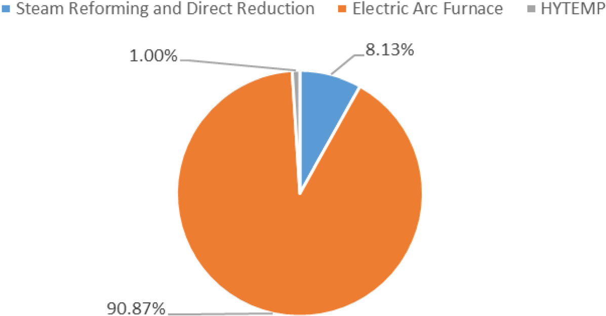
Figure 12 below is a Sankey diagram representing the energy flow in and out of the EAF for an operation with 100% Cold DRI (CDRI). A significant heat is lost in the form of exhaust gases from the EAF, reaching a value of 258 kWh per ton of liquid steel produced, which is almost 50% of the total electric energy required by the process. As such, recovering this thermal energy internally for preheating or power generation can substantially increase the energy efficiency of the process.
Sankey diagram of energy flow in and out of EAF per ton of liquid steel (kWh/t)
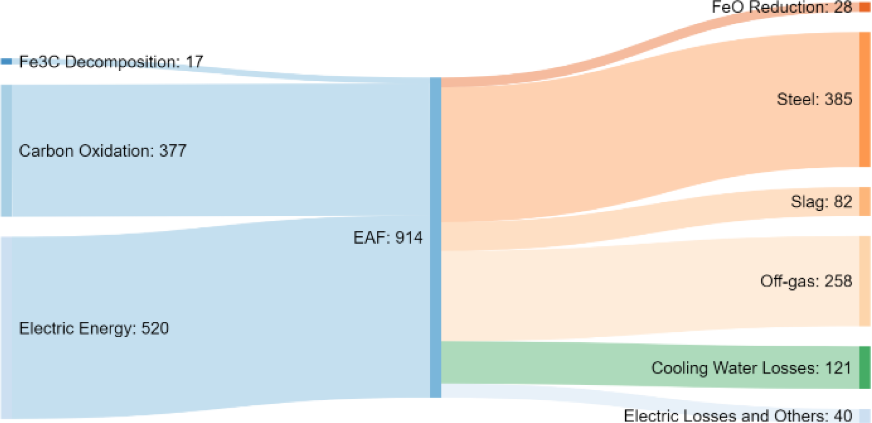
Table 6 illustrates the working limits and conditions for the ORC. Among the fluids used in this study, both R245fa and Cyclopentane matched the environmental and operational conditions with the highest performance.
Summary of the ORC operational conditions
| Parameter | Value |
|---|---|
| Turbine inlet vapor quality | 1 |
| Condenser Pressure (bar) | 1 - 2 |
| Condenser outlet water temperature (°C) | 30 |
| Minimum pinch temperature (°C) | 10 |
| HTF oil mass flow rate (kg/s) | 20 |
| Ambient temperature (°C) | 25 |
| Turbine efficiency | 75% |
| Pump efficiency | 75% |
Upon keeping a constant oil temperature, the resulting fluctuations in the mass flows of the oil loop and ORC fluids can be seen in Figure 13 below. As expected, they react to the exhaust gas fluctuations and replicate its behavior in order to adapt to the temperature constrains assigned. However, it can be noticed that the effect in terms of mass flow fluctuations on the ORC was much higher than in the Oil loop. Also, it is worth noting that the impact of fluid selection on mass flow fluctuations in the cycle is significant when comparing the high mass flow rate and high range of fluctuations with R245fa as opposed to using Cyclopentane as a working fluid. Consequently, Cyclopentane was investigated in a second implementation as an alternative ORC working fluid. In [33], laboratory experiments were executed to establish the maximum operating temperature for Cyclopentane as an ORC working fluid and both have proven that it is stable at the temperatures in which the studied system is operated in.
Simulation model's mass flows
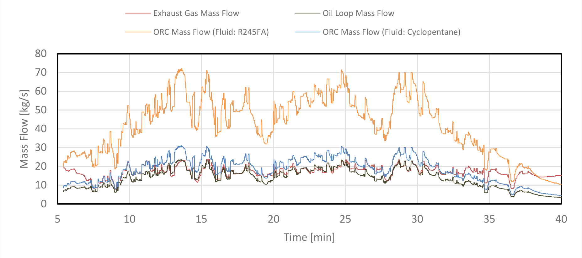
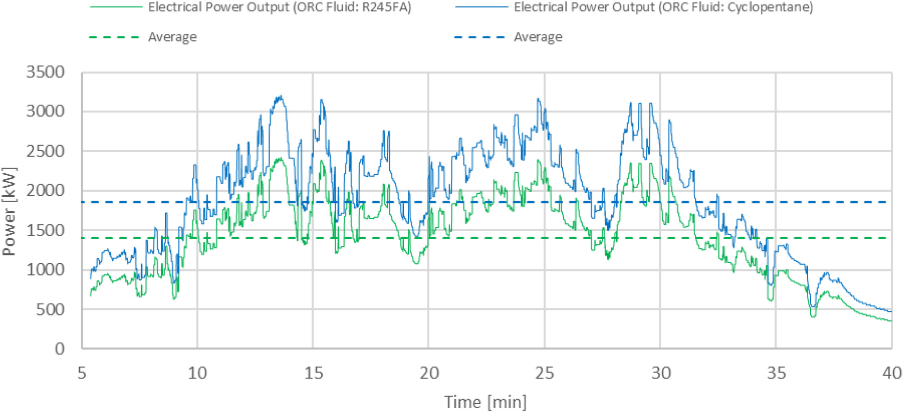
Figure 14 displays the power output using both R245fa and Cyclopentane with mass variation. The power fluctuation ranges between 350 to 2400 kW with an average of 1404 kW for R245fa whereas it ranges between 460 to 3150 kW with an average of 1862kW for Cyclopentane. This high fluctuation of power due to the varying mass flow would negatively affect the efficiency of a conventional turbine thereby makes it difficult to rely on such a system. Furthermore, having an appropriate design point of the heat exchanger and a turbine to operate in an off-design mode is a major challenge that would make the system unstable and impractical due to the high range of fluctuations.
Simulation model's generated power
By maintaining a constant oil mass flow, the resulting temperature profiles of the Concrete block and the HTF passing through it are presented in Figure 15. The CFD based block was simulated from a presumed ambient temperature and for around 4 days of physical time. In order to provide the required heat source for this model, the EAF exhaust gas reference cycle considered in the previous model was repeated and reconfigured as a continuous recurrent flow of heat from a plant that is running continuously for 4 consecutive days. The model was simulated for 4 days to be able to identify the time required to preheat the block after it starts operating.
TES block resulting temperatures
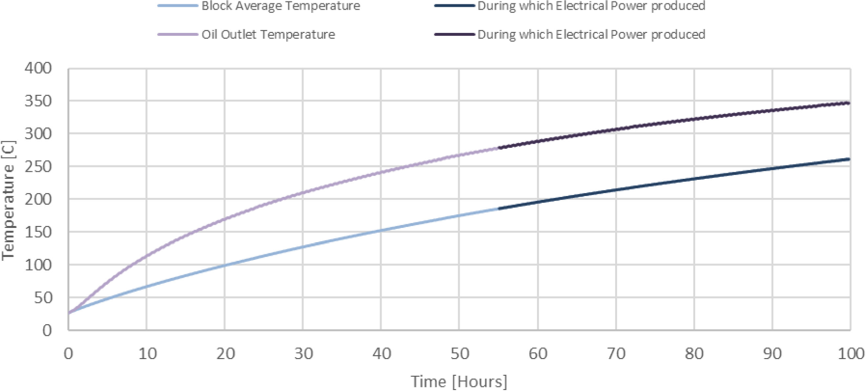
It can be seen that the fluctuations in temperature no longer exist and instead the temperature profiles are increasing in a steady manner. However, it has been noticed that it took more than 2 days to heat the block to the point where the HTF passing through it can result in the ORC operating and generating electrical power.
The exhaust gas and HTF were entering the block at the average temperature of 700 °C and 70 °C respectively. This can be seen in Figure 16 along with the heat flow and distribution across the block. During the simulation time, the Block average temperature and the Oil outlet temperature reached a value of 261 °C and 347 °C respectively. It is also noticed from the gas outlet contour that the gas pipes were fairly distributed, and this could be deduced from the evenly temperature reduction of the pipes. However, the temperature gained by the block is concentrated in the middle of the block reducing in higher temperatures of the oil outlet. According to the behavior of the obtained values, and if the exhaust gas keeps flowing through the assigned block pipes, the temperatures are anticipated to keep rising in a smooth manner until reaching a steady state value.
TES adjacent surfaces temperatures
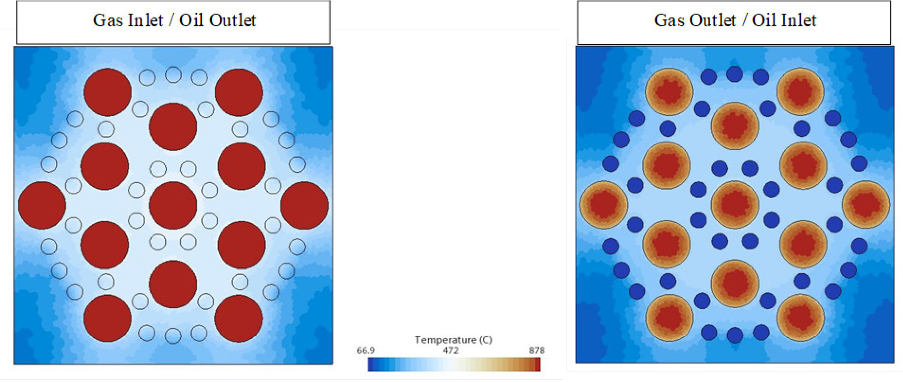
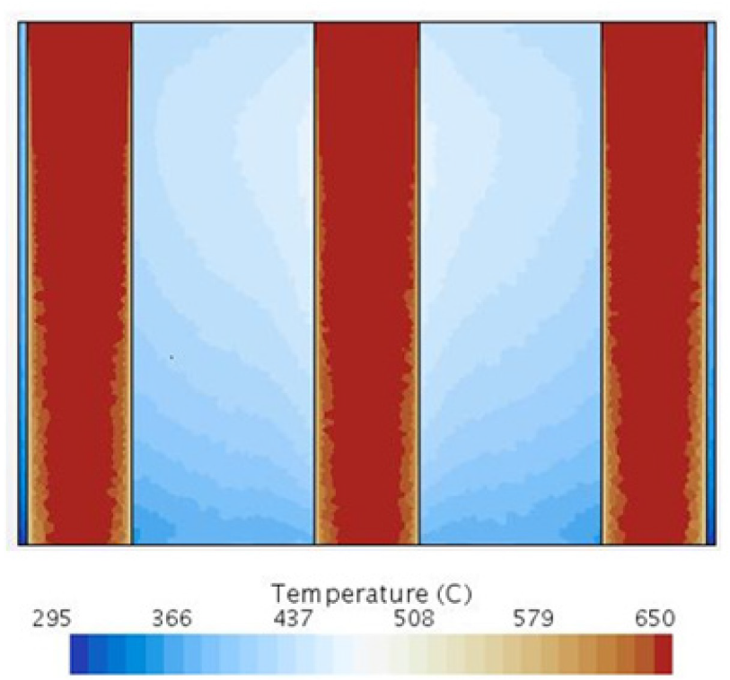
Figure 17 shows a cross-section in the middle of the TES cutting through the gas pipes and the solid concrete block. The temperature gradient in the mid-section varies between 366 °C to around 437 °C. This shows a good indication on the depth of the block although a slight temperature reduction near the oil outlet side.
TES middle cross-section
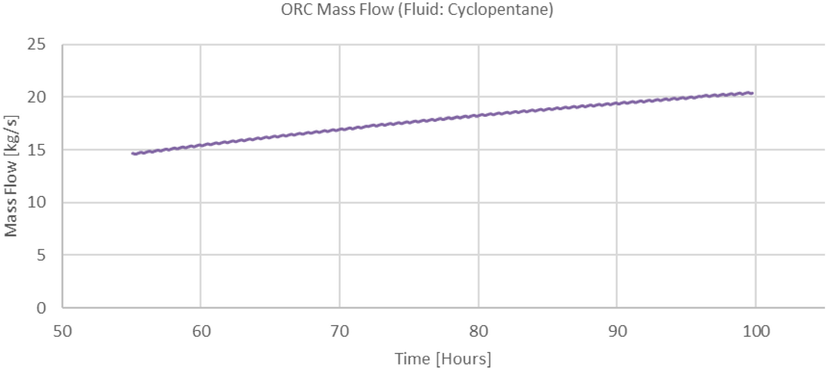
Since using Cyclopentane as the ORC working fluid in the Oil loop model has displayed better performance, it was straightforwardly considered as the working fluid for the ORC in the TES model. As can be seen in Figure 18, for the simulation duration in which the HTF was able to evaporate the ORC working fluid and generate electrical power, the mass flow increased steadily in response to the increase in the HTF temperature.
Model's ORC mass flow
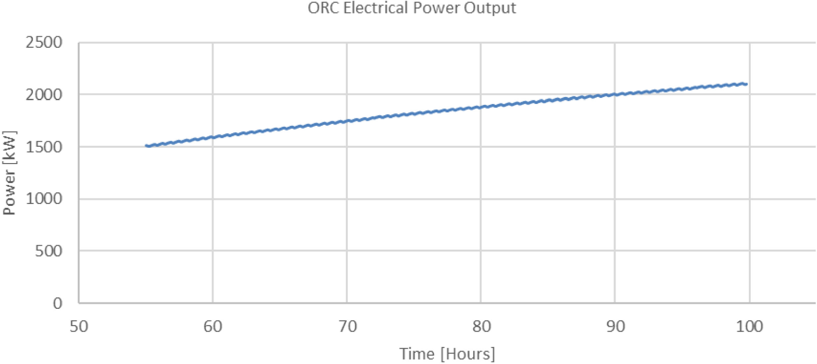
Consequently, the power generated at the Turbine outlet presented in Figure 19 had an analogous response as well. The outlet power kept increasing throughout reaching a value of 2108 kW at the end. Again, if the exhaust gas keeps flowing through the block for an extended time period, the Turbine outlet power is also anticipated to keep rising until reaching a steady state value that correspondence to the block average temperature and the HTF outlet temperature steady state values.
Model's ORC generated power
In a continuous charge of the EAF with a production capacity of 80-90 tons per TTT cycle, the average power of the off-gas from the EAF is about 7786 kW per cycle. Some of this is captured in the cooling water used in the EAF, and the remaining majority is captured by the waste heat recovery system. This excess heat can be re-used for water heating onsite, exported to other industrial plants, or can be utilized for district heating systems. If its temperature is low, the waste heat can be upgraded with heat pumps to steam for use onsite as mentioned, whereas if it is high, it can be used to generate electricity onsite [34]. The latter was the assumption for this study. Table 7 summarizes the potential of energy recovery in an EAF process with the WHR options considered in this study.
Improvement of the EAF Process with WHR Optionsž
| One TTT Cycle | 80-90 tons EAF | EAF connected to an Oil loop with an ORC | EAF connected to a TES with an ORC |
|---|---|---|---|
| Average power of the Off-gas | 7786 kW | 7786 kW | 7786 kW |
| Average recovered power | - | 1862kW | 2108 kW |
| % of Power recovered | - | 24% | 27% |
Using an Oil Loop coupled with an ORC, the average output power achieved during the considered time within 1 heat cycle of the EAF is 1862kW, indicating that up to 24 percent of power in the off-gas can be recovered and used to generate electricity. However, the power profile was accompanied with concerning fluctuations that may cause a significant vibrant operation problems and possible ORC components corrosion.
On the other hand, using a TES coupled with an ORC, within a simulation period of 4 days, an output power of 2108 kW was achieved, stipulating 27 percent of power in the off-gas can be recovered and used to generate electricity. Nevertheless, the last-mentioned value is anticipated to rise and reach a much higher steady state value in an extended period of time making it more stable and reliable for use onsite. To improve this efficiency further, it is important to consider a more accurate design specification of the TES Concrete model as the dimensions of the one developed in this study were straightly scaled up and used to prove the effectiveness of the proposed WHR model.
Finally, although the 80-90 tons EAF contemplated in the transient simulation of the WHR models is relatively lesser in term of its capacity than the 150 tons EAF considered in the steady-state simulation of the steel manufacturing plant, their average TTT time, and more importantly mass flow and temperature profiles are comparable and therefore the proposed WHR model is applicable to be used for both.
In this study, we simulated one phase of a steel manufacturing plant, and we investigated the potential of several waste heat recovery systems to recuperate the thermal heat content of the exhaust gases from the EAF. We simulated the process in the Aspen Plus ® environment to better understand the mass and energy flows through the system. A thermal energy storage is then designed in the STAR-CCM+ software to capture the heat content of the off-gas from the EAF. This consists of a high temperature concrete medium, and a heat transfer fluid, Therminol VP-1. Coupled with an Organic Rankine Cycle designed in IPSEpro for electricity generation via the turbine, the waste heat recovery model was implemented. Cyclopentane has proven more efficient and compatible to the fluctuations in the off-gas and was therefore used as the ORC working fluid. In a simulation period of 4 days, an output power of 2108 kW per TTT cycle was achieved from the off-gas of the EAF. Applying these recovery percentages to the 150 tons EAF in the plant of study relates that the WHR options can offset around 11.9% to 13.4% of the electric energy supplied to the EAF. We acknowledge that the limitations of this work include the continuous and consistent operation of the EAF, which in turn affects the efficiency of the WHR system. This is to be captured in future extensions of this work. Moreover, we are to consider the attempt of running the simulation for an extended period of physical time in order to identify the maximum steady state values that can be achieved from such an implementation. In addition, when designing a relatively large block as the one used for TES purposes, careful consideration is to be given to the creeping of concrete as it results in slits in between the oil pipes and the concrete block that will degenerate the heat conduction.
The authors recognize the financial support of Khalifa University under the internal grant CIRA-2018-97.
- , IEA (2020), Tracking Industry 2020, IEA, Paris, 2020
- ,
A brief overview of low CO2 emission technologies for iron and steel making ,J. Iron Steel Res. Int. , Vol. 17 (3),pp 1–7 , 2010, https://doi.org/https://doi.org/10.1016/S1006-706X(10)60064-7 - , 56 Emerging Technologies for Energy-efficiency and GHG Emissions Reduction in the Iron and Steel Industry
- , Heat: Vision 2030- Breaking down the barriers to citywide heat network deployment
- ,
Energy efficiency assessment: Process modelling and waste heat recovery analysis ,Energy Convers. Manag. , 2019, https://doi.org/https://doi.org/10.1016/j.enconman.2019.06.074 - , Global crude steel output increases by 4.6% in 2018
- ,
Off-Gas Waste Heat Recovery for Electric Arc Furnace Steelmaking Using Calcium Hydroxide (Ca (OH) 2) Dehydration ,Steel Res. Int. , Vol. 91 (11), 2020, https://doi.org/https://doi.org/10.1002/srin.202000048 - , Waste heat recovery in the steel industry: better internal use or external integration?, 2018
- ,
Applications and technological challenges for heat recovery, storage, and utilization with latent thermal energy storage ,Appl. Energy , Vol. 283 , 2021, https://doi.org/https://doi.org/10.1016/j.apenergy.2020.116277 - ,
Improving energy recovery efficiency by retrofitting a PCM-based technology to an ORC system operating under thermal power fluctuations ,Appl. Energy , Vol. 208 , 2017, https://doi.org/https://doi.org/10.1016/j.apenergy.2017.09.054 - ,
Dynamic optimal design of a power generation system utilizing industrial waste heat considering parameter fluctuations of exhaust gas ,Energy , Vol. 44 , 2012, https://doi.org/https://doi.org/10.1016/j.energy.2012.04.043 - ,
Thermal power fluctuations in waste heat to power systems: An overview on the challenges and current solutions ,Appl. Therm. Eng. , Vol. 134 , 2018, https://doi.org/https://doi.org/10.1016/j.applthermaleng.2018.02.033 - ,
A review of phase change materials for vehicle component thermal buffering ,Appl. Energy , Vol. 113 , 2014, https://doi.org/https://doi.org/10.1016/j.apenergy.2013.08.026 - ,
Thermal energy storage system integration forms for a sustainable future ,Renew. Sustain. Energy Rev. , Vol. 62 , 2016, https://doi.org/https://doi.org/10.1016/j.rser.2016.04.076 - ,
Buffer storage for direct steam generation ,Sol. Energy , Vol. 80 , 2006, https://doi.org/https://doi.org/10.1016/j.solener.2005.05.013 - , Inventory of Phase Change Materials (PCM), 2005
- ,
PCM-based energy recovery from electric arc furnaces ,Appl. Energy , Vol. 136 , 2014, https://doi.org/https://doi.org/10.1016/j.apenergy.2014.07.052 - ,
Enhancing energy recovery in the steel industry: Matching continuous charge with off-gas variability smoothing ,Energy Convers. Manag. , Vol. 104 , 2015, https://doi.org/https://doi.org/10.1016/j.enconman.2015.05.012 - , Technological Developments of ENERGIRON Direct Reduction Process: Latest Operating Results, 2016
- ,
Thermal energy storage for waste heat recovery in the steelworks: The case study of the REslag project ,Appl. Energy , Vol. 237 ,pp 708–719 , 2019 - , Aspen Plus Ammonia Model, 2015
- ,
ORC technology for waste-wood to energy conversion in the furniture manufacturing industry ,Therm. Sci. , Vol. 12 (4),pp 61–73 , 2008, https://doi.org/https://doi.org/10.2298/TSCI0804061M - ,
Enhancing energy recovery in the steel industry: Matching continuous charge with off-gas variability smoothing ,Energy Convers. Manag. , Vol. 104 , 2015, https://doi.org/https://doi.org/10.1016/j.enconman.2015.05.012 - ,
Techno-economic analysis of waste heat recovery with ORC from fluctuating industrial sources ,Energy procedia , Vol. 129 ,pp 503–510 , 2017, https://doi.org/https://doi.org/10.1016/j.egypro.2017.09.170 - ,
Working fluid selection for organic Rankine cycle (ORC) considering the characteristics of waste heat sources ,Ind. Eng. Chem. Res. , Vol. 55 (5),pp 1309–1321 , 2016, https://doi.org/https://doi.org/10.1021/acs.iecr.5b02277 - ,
Critical temperature criterion for selection of working fluids for subcritical pressure Organic Rankine cycles ,Energy , Vol. 74 ,pp 719–733 , 2014, https://doi.org/https://doi.org/10.1016/j.energy.2014.07.038 - ,
Investigation on the fluid selection and evaporation parametric optimization for sub-and supercritical organic Rankine cycle ,Energy , Vol. 96 ,pp 59–68 , 2016, https://doi.org/https://doi.org/10.1016/j.energy.2015.12.040 - ,
Guidelines for optimal selection of working fluid for an organic Rankine cycle in relation to waste heat recovery ,Energy , Vol. 96 ,pp 592–602 , 2016, https://doi.org/https://doi.org/10.1016/j.energy.2015.12.098 - ,
Performance prediction and working fluids selection for organic Rankine cycle under reduced temperature ,Appl. Therm. Eng. , Vol. 153 ,pp 95–103 , 2019, https://doi.org/https://doi.org/10.1016/j.applthermaleng.2019.02.011 - ,
Excess heat utilization combined with thermal storage integration in district heating systems using renewables ,Therm. Sci. ,pp 3673–3684 , 2020, https://doi.org/https://doi.org/10.2298/TSCI200409286D - ,
Embodied energy in thermal energy storage (TES) systems for high temperature applications ,Appl. Energy , Vol. 137 , 2015, https://doi.org/https://doi.org/10.1016/j.apenergy.2014.06.062 - ,
Electricity and Water Cogeneration Utilizing Aluminum Furnaces Waste Heat Integrating Thermal Storage Organic Rankine Cycle ,J. Sustain. Dev. Energy, Water Environ. Syst. , Vol. 9 (3), 2021, https://doi.org/https://doi.org/10.13044/j.sdewes.d8.0381 - ,
Thermal stability of working fluids for organic Rankine cycles: An improved survey method and experimental results for cyclopentane, isopentane and n-butane ,Appl. Therm. Eng. , Vol. 73 (1),pp 764–774 , 2014, https://doi.org/https://doi.org/10.1016/j.applthermaleng.2014.08.017 - ,
Case Study of an Organic Rankine Cycle (ORC) for Waste Heat Recovery from an Electric Arc Furnace ,Energies , Vol. 10 (5), 2017, https://doi.org/https://doi.org/10.3390/en10050649