


Rational energy management is a very important aspect when designing cooling plants. Energy savings in cooling plants are affected by the selection of the best, i.e. most optimal systems, i.e. solutions. An optimal system [1] is one that will provide maximum energy efficiency by minimizing electricity consumption, with a minimal noise level as required by the relevant professional rules applicable to plant installation sites, with minimal embedded dimensions and mass of the respective devices, offered at minimum cost. In addition, the solution must be technically feasible. It is also certainly necessary to consider the price of the designed plant, which refers to its economic feasibility. Ultimately, the solution must also be socially acceptable, e.g. consideration of its environmental impact.
In their efforts towards designing such solutions, on numerous occasions designers found themselves in situations where the decision-making process [2] was used to select the best alternative to the system architecture considering the initially defined investor requirements. The evaluation of the proposed system architecture alternatives is a very important task within the overall process of designing the system, both as a whole as well as each subsystem and component respectively [3]. Considering the entire decision-making process, the evaluation of the proposed alternatives in the process of designing cooling plants largely affects both the outcome of the decision-making process and subsequent system quality [1], [4]. The effective consideration of a set of alternatives and searching for the best solutions are an integral part of the designing process [3]. While approaching the goal, it is sometimes necessary to take into account different priorities in the selection of the best alternatives, by simultaneously analysing several different criteria.
As this paper is focused on cooling plant systems in industrial facilities (particularly in the industries of food and pharmaceuticals), it should be noted that the cooling plant system designed for these purposes must meet the requirements of ensuring the best possible working and living conditions, while maintaining optimal energy distribution and its consumption. It is also important to take into account the exterior operating conditions and types of energy-consuming devices within the facility. This, again, depends on the operating conditions and period of year, which the facilities are planned to be used in. It is of utmost importance to consider energy efficiency when designing a system. It is achieved by effectively defining the investor requirements at the very beginning of the system development process. It is of great importance within design offices nowadays as seeking new knowledge requires comprehensive and effective methods as well as tools to help the designer integrate the energy aspects during the design process. New approaches are still being investigated and can be said to be necessary [5], including a unified approach presented by the authors in this paper.
In this section, the authors present the literature survey needed to review existing obtained research on multiple touch points to which the approach presented in this paper supplements. Above all, this is meant to review existing methodologies, approaches, methods and tools that are related to the system architecture development.
Firstly, it is necessary to mention a structured methodology called DfV, which was developed to help design teams to reduce the impact of variety on the life-cycle costs of a product [6]. Also, a methodology developed from Galsworth [7], which describes a VEP, a methodology to help companies decrease the complexity of variety. In addition, there are various developed optimization techniques to estimate the best product architecture as outlined in Fujita et al. [8]. On the other hand, Tseng and Jiao [9] developed a PFA model, which has the purpose of handling the trade-offs between the diversity of customer requirements and design reusability as well as process capabilities. They also want to mention Nayak et al. [10] who present a VBPDM, which aims to satisfy a range of performance requirements using the smallest variation of product designs in the family. It is also important to mention the works of Claesson et al. [11], who modelled product platforms using configurable components and the paper from Pedersen et al. [12], who present a systematic domain-independent engineering approach to design hierarchical product platforms based on similarity or commonality within complex engineering systems. Secondly, some methodologies are mentioned for the evaluation and validation of product variants. Lechener et al. [13], present in their paper the development of a model-based evaluation approach of variant-driven complexity in the automotive industry by capturing relevant product variety driven costs and performance impacts. The evaluation of product families due to their complexity is described in the methodology given by Rissanen et al. [14]. In addition to all the above, there are also methodologies based on DoE, such as a validation process for complex products [3]. Below, there are preceding works that describe the product selection tool overview. Some tools for supporting the selection of configurable products and avoiding iteration caused by wrong product selections were most directly addressed by Pargamin [15]. There are also many tools and methods that make product selection possible regarding off-the-shelf products, analysed, described in the literature such as by Ardissono et al. [16]. Heiskala et al. [17] describe a practical web-based tool called CCP that extends analytical product selection to configurable products.
It is also necessary to mention the author Ulmann [18], who specifies several evaluation methods relating to the conceptual phase of the designing process and distinguishes between two main categories. The first category comprises absolute methods, which means that each concept is compared against a set of designing requirements. In the second category, the methods are based on a relative comparison between concepts. In Ulmann [18], very generically describes how concepts are created, including their generation, evaluation and the relevant decision-making (as an iterative process). All this is documented and discussed, and certain concepts are later detailed and then refined, approved or rejected.
Duda [19] show the overall methodology for creating an energy-efficient cooling plant, where decisions are based on the Simple Payback Method and the USPWF to calculate the costs of the energy to be used in each year of the product’s lifecycle. It uses a slightly different approach than the one shown in the paper of Osman et al. [20] where the price was calculated on the basis of the energy actually used for each day and each month analysed based on the average outside air temperature on the basis of data actually received for several years preceding the research year.
Osman et al. [1] describe and present a methodology for the development of cooling plant architectures, which comprises 4 basic steps and is also presented graphically through a flow chart. This methodology is iterative, i.e. several steps need to be completed to obtain the desired chiller plant architecture. The steps included in the methodology are:
Definition of customer (investor) and engineering requirements;
Equipment selection in cooling plant through several sub steps:
Chiller(s) selection;
Cooling tower(s) selection;
Dry cooler(s) selection;
Circulation pump selection on condenser and evaporator sides of cooling plant;
Pipeline dimensioning;
Selection of fittings and measuring and automatic control equipment;
Evaluation analysis;
Change phase in customer (investor) needs and engineering requirements and equipment selection. The methodology is partly implemented by using analytical methods and partly by using manufacturer software (system configurators), as used by the authors in their practical work.
Osman et al. [4] presents and describes in detail the approach for the chiller selection in step 2a) of the methodology described in Nayak et al. [10]. The approach is divided into several phases:
Configuration phase;
Modification phase;
Evaluation phase.
Efforts were made to present and explain in greater detail the approach to the configuration of one of the main subsystems within the cooling plant system (with air and water cooled chillers) and that modifications to its system architecture may be made and evaluated for the purpose of obtaining a satisfactory solution.
In their most recent paper, Osman et al. [20] presented an evaluation method relating to step 3 which comprises the following 12 steps:
Gather outside temperature data;
Calculate average outside temperature;
Define observed cooling effect;
Determine average cooling effect of each system architecture;
Calculate electric power for each component of observed system architecture;
Determine average electric power for each component of observed system architecture;
Calculate cooling water losses on cooling tower (optional);
Calculate electricity consumption;
Calculate cooling water consumption (optional);
Calculate total price of electricity consumed;
Calculate total price of cooling water consumption (optional);
Compare proposed system architectures. This method is of analytical nature, quite complex, and serves mostly to effectively resolve any issues in the selection of the cooling plant architecture system.
This paper is intended to complete a unit by combining the research collected to date and presented in [1], [4], [20] as a proposed unified approach to the designing of such cooling plants. In addition, a more detailed description of the approach is described through approach verification on an example of a cooling plant with water-cooled chillers.
A designer encounters a variety of engineering problems when designing a cooling plant, the difference between them depends on how the designer views them, i.e. the sequence used to resolve such problems. What is common to all designing problems is that they need to be resolved within a set time and have their defined limitations, i.e. available resources. In addition, the solution must be appropriate to the level of technical abilities existing at the time of resolving the problem. To avoid drifting from the goal in the process of designing a cooling plant system (and in the decision-making process [2]) regarding the best-proposed designer solution for the cooling plant design (especially in case of younger and inexperienced designers), this paper aims to complete a unit in the presentation of the proposed approach to the designing of such plants. The authors aimed to expand and integrate all research gathered and published in their earlier papers [1], [4], [20], enlarge all this and thoroughly explain the other steps of the methodology as specified in their papers [1].
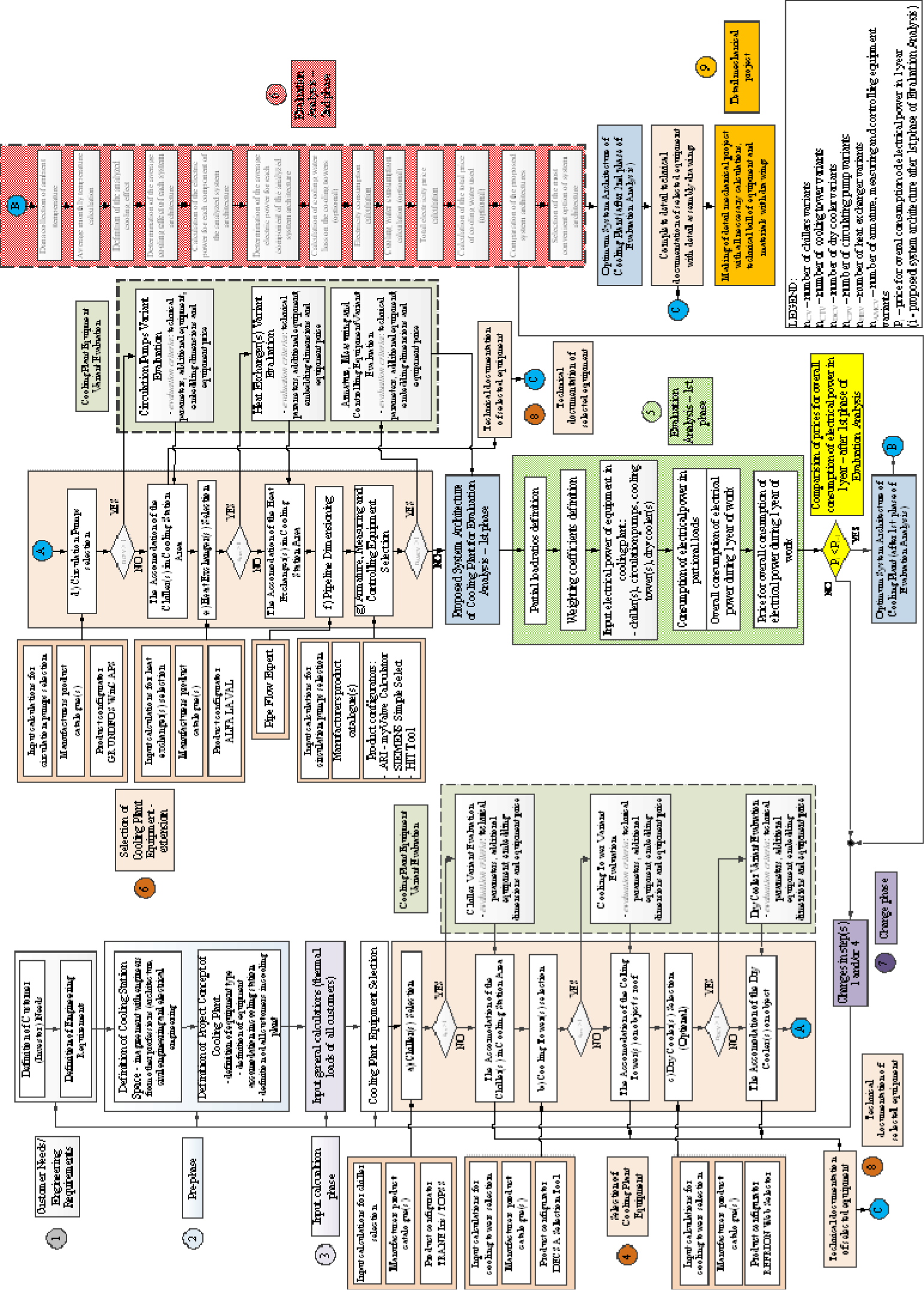
This section provides an overview of a unified approach when developing system architecture in energy efficient designs for cooling plants (Figure 1). The presented approach is described below, which comprises nine basic steps. As seen in the text below and in the flow diagram in Figure 1, the approach is iterative, i.e. several steps need to be completed to obtain the desired (optimal) cooling plant architecture. These steps include a loopback step, which allows changes to be made to any or all steps of this approach (steps 1-4). It should also be mentioned that the approach has not yet been fully computer-implemented and is partly implemented by using analytical methods and manufacturer software (system configurators), as used by the authors in their work. It is important to note that the proposed approach is also applicable to software supplied by manufacturers of similar (equivalent) equipment. This section merely lists the respective steps of the presented approach. Such steps will be detailed through an example in the next section. The steps comprising this approach are:
Define customer (investor) and engineering requirements [21];
Pre-phase comprising two sub steps;
Define cooling plant installation space;
Define cooling plant concept;
Estimate input phase;
Select different cooling plant equipment – this includes several sub steps;
Chiller(s) selection [22];
Cooling tower(s) selection;
Dry cooler(s) selection (optional);
Circulation pump selection on condenser and evaporator sides of cooling plant;
Heat exchanger(s) selection (optional);
Selection of other cooling plant equipment;
Pipeline dimensioning [23];
Selection of fittings and equipment for measurement and automatic control.
Each of the sub steps includes an input calculation for the selection and the selections are made using manufacturer catalogues and software (system configurators).
It should be noted that, in case there are several variants for any of the selected equipment (the number of variants is greater than 1) in any sub step, the variants need to be evaluated against the following criteria: technical parameters of the equipment, additional equipment, embedded dimensions and price of equipment. In this paper, the authors proposed the types of equipment and the configurators provided by the manufacturers that they normally use for designing this type of plant. Of course, the approach is applicable to other equivalent equipment provided by other manufacturers.
A so-called CCM) approach [24] is used for all types of equipment [sub steps (a)-(e)] – for example, it selects an optimal system solution when selecting the chiller, i.e. the chiller that will provide maximum energy efficiency by minimizing electricity consumption, with a minimal noise level as required by the relevant professional rules applicable to plant installation sites, with minimal embedded dimensions and mass of the respective devices, offered at minimum cost. After selecting each piece of equipment, it needs to be checked and placed within the cooling station area;
Evaluation analysis of proposed system architectures (phase 1). Phase 1 of the evaluation analysis is implemented for the proposed system architecture variants defined in the preceding steps. It is based on calculating the total electricity consumption during one year for each of the proposed system architecture variants;
Evaluation method for proposed system architectures (phase 2). A more detailed evaluation analysis is conducted based on one or several proposed system architectures found to be satisfactory based on the evaluative analysis performed as part of phase 1, including the following sub steps;
Gather outside temperature data;
Estimate average monthly temperature;
Define observed cooling effect;
Determine average cooling effect of each system architecture;
Estimate electric power for each component of observed system architecture;
Determine average electric power for each component of observed system architecture;
Estimate cooling water loss on cooling towers (optional);
Estimate electricity consumption;
Estimate cooling water consumption (optional);
Estimate total electricity price;
Estimate total price of cooling water used (optional);
Compare system architectures proposed in phase 2;
Change phase. As mentioned, the presented unified approach is iterative, i.e. it is envisaged that changes may be made using a loopback step, e.g. both in customer requirements and in the equipment selection sub steps, so that a subsequent evaluative analysis could result in an optimal cooling plant system architecture in terms of energy efficiency, i.e. electricity consumption (steps 1-4);
Generate technical documentation for each piece of selected equipment;
Develop cooling plant executive design.
Graphical representation of proposed unified approach – flow diagram
This section presents the verification of the approach to creating engineering executive designs for cooling stations. As an example for such verification, they selected a cooling plant designed to operate in the pharmaceutical industry, located in North Croatia (town Ludbreg). It was known at the very start that the cooling station system would comprise the following subsystems: a cooling energy source (a chiller or several of them), the condenser part of the cooling plant (several cooling towers, condenser pumps, armature, measuring elements and the associated pipelines), the evaporator part of the chiller plant (evaporator pumps, several dry coolers, armature, measuring elements and the associated pipelines), and automated control of the plant. The project is then implemented according to the steps of the approach specified in the preceding section.
In consultation with the customer (investor), a list of requirements is created, based on which initial engineering requirements for designing the cooling station are defined [21]. Such customer requirements are as follows:
The cooling plant is located in North Croatia;
The cooling plant must be designed and built for indoor installation, provided that the cooling towers, dry coolers, pipelines and associated fixtures and part of the measuring equipment will be located outside the facility;
The cooling plant must be capable of operating in variable exterior operating conditions (winter/summer modes and interim modes between these two modes);
The cooling plant is designed for industrial cooling/heating processes and comfortable air conditioning in certain areas in the pharmaceutical industry;
Considering the distance to the inhabited area, “silent operation” of the cooling plant must be ensured in daytime;
The cooling plant must be capable of being automatically operated.
The engineering requirements based on such customer requirements are as follows:
The cooling plant must have uninterruptible power supply of 3 × 380 V, 50 Hz;
The cooling plant must be capable of operating all day (24 h) and every day of the year (365 days);
The cooling plant must be allowed to operate in the so-called free cooling during part of the winter and transition periods;
A certain number of chillers will be selected based on the defined cooling load of the facility and the types of energy-consuming devices (in certain parts of the winter mode period and in transition mode periods);
It must be ensured that the selected chillers comply with the relevant levels of acoustic pressure as defined in the legislation applicable to such types of working areas;
The chillers must be able to operate in parallel work;
The temperature of chilled water on the evaporator side of the plant must range between 6-12 °C;
The temperature of chilled water on the condenser side of the plant must range between 29-35 °C.
Includes two steps:
Define cooling plant space. In consultation with engineers from other fields (architecture, civil engineering and electrical engineering) the entire area to be occupied by the chiller station will be defined so as to allow proper placement of all devices and installations required for the proper operation of the plant;
Define cooling plant concept. This step is used to define types of equipment, accommodation of equipment within the chiller station area, and all energy-consuming devices in the chiller plant.
Based on the data gathered in the first three steps, general estimates are made (such as the estimate of heat losses and gains for the entire facility).
This includes several sub steps:
Chiller selection. According to the data about the total cooling load, the temperature modes on the evaporator and condenser sides of the system, coolants, acoustic pressure levels, energy class of the device] including minimum values of EER, ESEER and COP, and accommodation of the device (i.e. its dimensions), the types and number of chillers are selected. When selecting chillers, the authors used product configurators provided by “TRANE” Iris and TOPSS. The selection of equipment was based on the total defined energy-consuming load in the facility. In this case, it amounted to 6,500 kW. As this is a relatively high load, they selected three chillers: two with centrifugal compressors and one with a screw compressor. This example shows the selection of TRANE equipment for the chillers;
Cooling towers selection. They are selected based on the data about the selected chillers (total installed cooling load and supplied electric power of the devices – from the preceding sub step 4a), including, of course, the defined temperature mode on the condenser side and the ambient temperature. Depending on which products are offered, the intended purpose of the plant and the ability to accommodate the cooling towers, their type and number are selected. A configurator provided by “DESCA”, DESCA selection tool, is used to select the cooling towers;
Dry coolers selection (optional). Dry coolers are selected to allow the chiller plant to operate in winter mode and sometimes in transient mode because they allow for so-called free cooling. Their selection requires information about the number of energy-consuming devices, as well as their cooling load in such operating modes. They also need information on the supplied electrical power, in addition to the coolant temperature mode, and the ambient temperature below which they anticipated that the devices will work. A configurator provided by “REFRION”, REFRION web selector, is used to select dry coolers. They also selected two dry coolers with axial fans from said manufacturer;
Circulation pump selection on condenser and evaporator sides of cooling plant. Pumps are selected based on the defined temperature modes and the flow of medium on the condenser and evaporator sides. The number of circulator pumps is determined based on the types of energy-consuming devices, the size of the cooling plant and, consequently, the flow rate of medium, and calculated pressure drops in the pipeline branches. A spare (passive) pump must always be included in the selection. In addition to the pumps, frequency converters are defined as necessary in case of variable flow operation. A configurator provided by “GRUNDFOS”, WinCAPS, is used to select circulator pumps;
Heat exchanger(s) selection (optional). This is done in case the coolant circuits are intended to be separated in the primary and secondary circuits. It is in particularly used in a free cooling mode.
Select other chiller plant equipment. This refers to the selection of cooled water dividers/pots (their dimensions depend on the number of energy-consuming devices and their needs for cooling energy), selection of a coolant buffer, selection of y expansion tanks, selection of the cooling station water preparation system, etc.
System pipeline dimensioning. After selecting all necessary mechanical equipment and placing it in the intended plant area, the pipeline is dimensioned according to the defined coolant flow rates and pressure drops in all subsystems. For this purpose, the authors used the “Pipe Flow Expert” software made by Daxesoft Ltd [8], which is capable of rendering 3D pipeline models;
Selection of fittings and measuring and automatic control equipment. To select the fittings, the authors use the following software (product configurators) provided by “ARI Armaturen”, ARI – myValve Calculator, and by “IMI Hydronic Engineering”, HySelect, whereas they use software (product configurators) provided by “SIEMENS”, SIEMENS Simple Select and HIT Tool, to select the measuring and controlling equipment.
Each of the sub steps includes an input calculation for the selection and selections are made using manufacturers’ catalogs and software (system configurators). It should be noted that, in case there are several variants for any of the selected equipment (the number of variants is greater than 1) in any sub step, the variants need to be evaluated against the following criteria: technical parameters of the equipment, additional equipment, installation dimensions, and price of the equipment. In this paper, the authors proposed types of equipment and their configurators provided by manufacturers they normally use for designing this type of plant. Of course, the approach is applicable to other equivalent equipment provided by other manufacturers.
As it is previously noticed, a so-called CCM approach is used for all types of equipment [sub steps (a)-(e) of Section 4] – for example, it selects an optimal system solution when selecting the chiller, i.e. the chiller that will provide maximum energy efficiency by minimizing electricity consumption, with a minimal noise level as required by the relevant industry rules applicable to this type of facility, with minimal installation dimensions and weight of the respective devices, offered at minimum cost.
After selecting each piece of equipment, it needs to be checked and placed within the cooling station area.
Phase 1 of the evaluative analysis is implemented for the proposed system architecture variants defined in the preceding steps. It is based on calculating the total electricity consumption during one year each of the proposed system architecture variants. To conduct this analysis, they need the amount of electricity used in one year according to the defined energy-consuming devices in the facility and the electricity price (HRK/kWh), according to which the select optimal cooling plant architecture. It is necessary to define in this process the weighting coefficients according to the types of such energy-consuming devices and their operation throughout the year, i.e. the share of each partial or full system load. Phase 1 of the evaluative analysis is implemented for the purpose of defining the initial system architecture, i.e. whether the system will, for example, use pumps to generate variable flow in the system’s primary circuit or a combination of variable flow in the primary circuit and constant flow in the secondary circuit will be more feasible considering the types of energy-consuming devices.
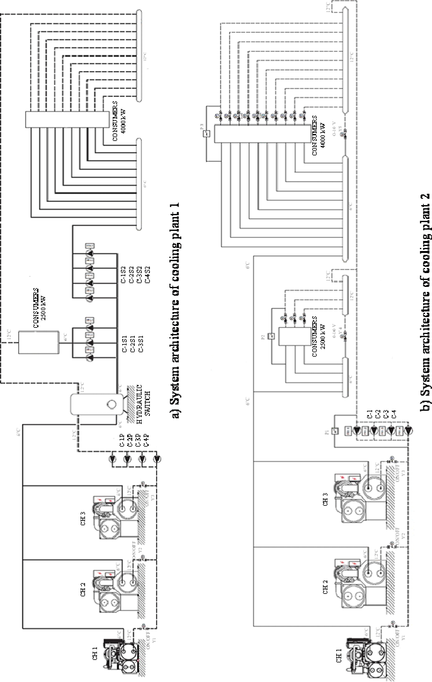
For this purpose, they proposed two system architectures. The first system architecture (iteration step 1) presents (see Figure 2a) the evaporator side of the chiller plant with constant water flow through the primary circuit and variable flows through secondary circuits of energy-consuming devices. In this case, both the primary and secondary circuits are mutually separated by a system balancing hydraulic switch. The second system architecture (iteration step 2) presents (see Figure 2b) variable-flow circulator pumps (with frequency converters) in the primary circuit. This eliminated the need for circulator pumps in the secondary circuit and thus reduced the space needed for the equipment in the chiller plant. They also need less wiring for this equipment.
They proceeded with the evaluation based on the system architectures proposed in iteration steps 1 and 2.
For this purpose, they first conducted an analysis of electricity consumption for the chiller plant with constant flows through the primary circuit and secondary circuits of energy-consuming devices to allow them to possibly compare further analyses (see Table 1).
It should be noted that no analysis was conducted for the condenser part of the chiller plant because, in designers’ experience, the electricity consumption level was assumed to be insignificant compared to the consumption in the evaporator part.
Suggested system architectures of cooling plants – evaluation analysis – phase 1
Evaluation analysis – phase I – cooling plant with constant volume flow through primary and variable volume flow through secondary plant circuit
| Partial load ratio [%] | Weighting coefficient [%] | Working time [h] | Input electrical power for circulating pumps N [kW] | Consumption of electrical power [kWh] |
|---|---|---|---|---|
| 100 | 3 | 262.8 | 244.84 | 64,343.95 |
| 75 | 33 | 2,890.8 | 181.12 | 523,581.70 |
| 50 | 41 | 3,591.6 | 163.11 | 585,825.88 |
| 25 | 23 | 2,014.8 | 81.57 | 164,347.24 |
| Working time in 1 year [h] | 8,760 | Overall consumption of electrical power in 1 year [kWh] | 1,338,098.76 | |
| Price for overall consumption of electrical power in 1 year [HRK] | 936,669.13 |
Evaluation analysis – phase I – cooling plant with variable volume flow through primary plant circuit
| Partial load ratio [%] | Weighting coefficient [%] | Working time [h] | Input electrical power for circulating pumps N [kW] | Consumption of electrical power [kWh] |
|---|---|---|---|---|
| 100 | 3 | 262.8 | 197.8 | 51,981.84 |
| 75 | 33 | 2,890.8 | 128.5 | 371,467.80 |
| 50 | 41 | 3,591.6 | 76.71 | 275,511.64 |
| 25 | 23 | 2,014.8 | 31.64 | 63,748.27 |
| Working time in 1 year [h] | 8,760 | Overall consumption of electrical power in 1 year [kWh] | 762,709.55 | |
| Price for overall consumption of electrical power in 1 year [HRK] | 533,896.68 |
A more detailed evaluative analysis is conducted based on the proposed system architecture found to be satisfactory based on the evaluative analysis performed as part of phase 1. This phase observes two system variants – variant 1 with cooling tower in the free cooling mode and variant 2 with dry coolers in the free cooling mode. The method includes the following sub steps:
Gather outside temperature data. Outside temperature data are gathered for the observed months of plant operation throughout the year, namely for the chiller station site, for each day of each month and each hour of each day. In addition to onsite measurements, such data may be obtained from the Meteorological and Hydrological Service of the Republic of Croatia. To obtain more accurate results, they assumed it would be advisable to collect data for several years back (e.g. up to 5 years) for the observed months intended to be analyzed. For that purpose, they observed the following months in the year: January, February and December for the winter mode and March, October and November for the interim mode of operation;
Estimate average monthly temperature. The average outside temperature must be calculated for each day of the observed month for a particular time interval, e.g. 3 hours each (8 time intervals during the observed day of 24 h) over several years;
Define observed cooling effect. Based on the operating mode, the observed cooling plant architectures are compared against (compressor cooling or free cooling mode) and the average outside temperature values for each interval during the observed day (from the preceding sub step 5b), the cooling effects that may be provided by chiller plant components in the observed system architectures (chillers, cooling towers, dry coolers, etc.) are defined. It should be noted that, depending on the outside temperature, especially if they analyze low outside temperatures (free cooling mode), these components will operate under reduced load (in case of water chillers) and at lower rotational speeds (in case of dry cooler/cooling tower fans);
Determine average cooling effect of each system architecture. They determine the average cooling effect depending on the desired operating mode under analysis and for those intervals of a day when our system components are intended to operate for each system architecture observed;
Estimate electric power for each component of observed system architecture. The total supplied electric power is determined for each component of the observed system architecture (such as the cooling towers, dry coolers, circulator pumps on the evaporator and condenser sides of the plant);
Determine average electric power for each component of observed system architecture. The average electric power is determined for each observed time interval during which a particular plant operating mode was analyzed based on the electric power calculated ( in the preceding step) for each system component;
Estimate cooling water loss on cooling towers (optional). The losses of cooling water are determined in case the observed system architecture includes a cooling tower component for a particular time interval during the observed day;
Estimate electricity consumption. Each component’s electricity consumption is determined according to a predefined duration of each interval and according to the estimated electrical power for each component of the observed system architecture (step e). The total electricity consumption is determined for each component for each observed day of the month and the total energy consumption is determined for each observed month;
Estimate cooling water consumption (optional). Again, the consumption of cooling water is determined according to a predefined duration of each interval and according to the estimated cooling water losses on the cooling towers (sub step 5g). Consumption levels are also determined for each day of the month, as well as total cooling water consumption for each observed month;
Estimate total electricity price. The total price of the electricity used is determined according to the total consumption of electricity for each observed month in the analysis (step h) and according to the defined unit cost of electricity used;
Estimate total price of cooling water used (optional). According to the total consumption of cooling water for each observed month (sub step 5i) and the defined unit cost of such cooling water used, the total price of cooling water used is determined;
Compare system architectures proposed in phase 2. Based on the data concerning electricity consumption, the total price of the electricity used, and the total price of energy used (including the price of electricity and the cooling water used), the proposed system architecture is compared for each observed month in the relevant operating mode and in aggregate for all months in a year. The more cost-effective option with a lower price of energy is selected based on the results obtained. To better illustrate the comparison between options, EER may be calculated for the observed system architecture options both for a single day in the observed month and as the average EER for a fully observed month.
As mentioned, the presented approach is iterative, i.e. it is envisaged that changes may be made using a loopback step, e.g. both in customer requirements and in the equipment selection sub steps, so that a subsequent evaluative analysis could result in an optimal cooling plant system architecture in terms of energy efficiency, i.e. electricity consumption (steps 1-4). In this example, two iteration steps were modified in phase 1 and phase 2 of the evaluation analysis.
Workshop drawings for each piece of chiller plant equipment are completed based on the selection of the final optimal system architecture and documents received from each manufacturer.
It is completed based on previously obtained data and estimates made, as well as the equipment documentation received from manufacturers (from the preceding step).
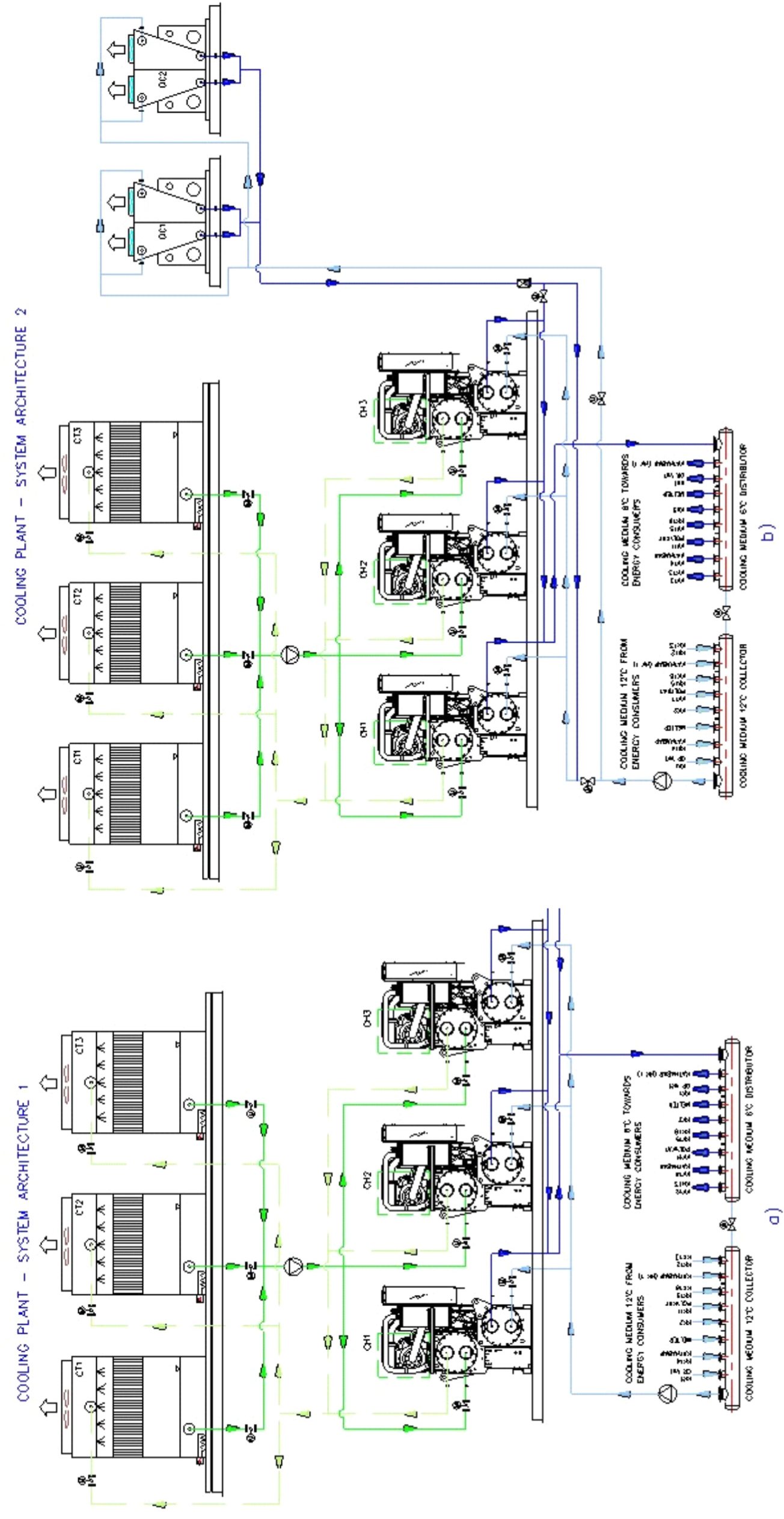
For the purposes of the phase 2 evaluative analysis, they created an algorithm using software MS Excel, which allowed us to calculate energy consumption for the two proposed cooling plant system architectures, presented in Figure 3. They considered system architecture option 1 with cooling towers and system architecture option 2 with dry coolers operating in the free cooling mode.
Suggested system architectures of cooling plants – evaluation analysis – phase 2
Phase 1 of the evaluation analysis of the proposed cooling plant alternatives is presented in Table 2a-c. There, several system architecture solutions are compared [system with constant volume flow through the entire evaporator part of the plant, system with constant volume flow through the primary circuit and variable volume flow through the secondary circuit of the plant (energy-consuming device circuit) and system with variable volume flow through the primary circuit of the plant)]. Based on the different types of energy consuming devices in the secondary circuit, a system operation is also defined in various modes throughout the year.
The comparison presented immediately leads to the conclusion that an acceptable solution, i.e. an alternative to be selected, should be sought in a cooling plant using circulation pumps with a variable flow in the primary circuit of the plant. If they compare this solution to a constant flow solution, the savings may reach up to 43% in terms of electricity price. However, in other cases not presented and considered in this case study, an acceptable solution could probably be a combination of a constant flow primary circuit and variable flow secondary circuit. Of course, all this depends on the proposed cooling plant architecture. In the case presented, no evaluation analysis was conducted for the condenser part of the cooling plant, because its energy consumption is insignificant compared to the electricity consumption in the evaporator part of the plant. In addition, the architecture of that part of the system remained the same through all iteration steps, i.e. it did not change. It should also be mentioned that partial system load gradations were made with 25% increments, which does not necessarily need to be a rule (load gradations possible with smaller increments). The design of the cooling plant, in this case being the presented solution with VPF also requires a more complex automatic control system compared to other system solutions. It is important to underline that the energy efficiency and operating reliability of the cooling plant also depend on the software controlling such a complex technical system. A subsequent evaluation analysis was performed for these two cooling plant concepts (1 and 2 in the text). For that purpose, a comparative table for the two concepts was created (see Table 2).
The table shows a comparison of the following operating modes: winter mode (January, February and December) and transitional operating periods during the year (March, October and November).
Evaluation analysis – phase 2, system architecture option 1 – cooling plant with cooling towers in free cooling mode
| System architecture option 1 – with cooling towers in free cooling mode | |||||
|---|---|---|---|---|---|
| Month | Consumption of cooling water Vcw1 [m3] | Consumption of electrical energy Eel1 [kWh] | Total cost of consumed cooling water Ccw,tot1 [HRK] | Total cost of consumed energy Ctot1 [HRK] | Average value of factor EER per months EERpost1 [-] |
| January | 1,496.91 | 50,769.20 | 22,453.65 | 49,361.32 | 15,213 |
| February | 1,392.87 | 45,095.34 | 20,893.05 | 44,793.58 | 13,277 |
| March | 1,184.64 | 37,291.98 | 17,769.60 | 37,534.35 | 11,950 |
| October | 481.65 | 14,630.40 | 7,224.75 | 14,978.86 | 5,529 |
| November | 936.27 | 29,481.54 | 14,044.05 | 29,669.27 | 10,358 |
| December | 1,495.32 | 49,631.37 | 22,429.80 | 48,734.43 | 14,363 |
| Total | 6,987.66 | 226,899.83 | 104,814.90 | 225,071.81 | |
Evaluation analysis – phase 2, system architecture option 2 – cooling plant with dry coolers in free cooling mode
| System architecture option 2 – with dry coolers in free cooling mode | |||
|---|---|---|---|
| Month | Consumption of electrical energy Eel1 [kWh] | Total cost of consumed energy Ctot1 [HRK] | Average value of factor EER per months EERpost1 [-] |
| January | 50,769.20 | 49,361.32 | 15,213 |
| February | 45,095.34 | 44,793.58 | 13,277 |
| March | 37,291.98 | 37,534.35 | 11,950 |
| October | 14,630.40 | 14,978.86 | 5,529 |
| November | 29,481.54 | 29,669.27 | 10,358 |
| December | 49,631.37 | 48,734.43 | 14,363 |
| Total | 226,899.83 | 225,071.81 | |
Evaluation analysis – phase 2, compression between system architecture option 1 and 2
| Comparison between system architecture option 1 and 2 | |||
|---|---|---|---|
| Month | Difference in electrical energy consumption ΔEel[kWh] | Difference in total cost of consumed electrical energy ΔCel,tot[HRK] | Difference in total cost of consumed electrical energy ΔCtot [HRK] |
| January | 35,391.25 | 18,757.36 | 41,211.01 |
| February | 49,744.81 | 26,364.75 | 57,320.70 |
| March | 21,881.88 | 11,597.40 | 29,367.00 |
| October | 7,341.30 | 3,890.89 | 11,115.64 |
| November | 17,007.07 | 9,013.75 | 23,057.80 |
| December | 33,736.64 | 17,880.42 | 40,310.22 |
| Total | 131,366.30 | 69,624.14 | 162,072.14 |
In this case, the operating modes are considered and the observed months of operation over a year, depending on the location of the cooling plant (North Croatia, City of Ludbreg). It may be concluded based on the analysis and its results that concept 2, proposed with dry coolers with a view to save energy, is definitely more cost-effective.
The reason is in the design of the dry cooler subsystem, which is closed and allows the system to operate at lower outside temperatures (for example, below 4 °C) with fans using EC motors. It may be concluded that the entire investment will have a payback period of approximately 5.4 years of use, i.e. operation of the cooling plant.
This paper presents research, i.e. a unified approach to describe the system architecture development in energy efficient design for cooling plant systems. The approach is based on selecting an optimal cooling plant system solution, which will provide maximum energy efficiency by minimizing electricity consumption, with a minimal noise level as required by the relevant industry rules applicable to the plant installation site, with minimal installation dimensions and weight of the respective devices, offered at minimum total cost.
The approach is based on the authors’ years of experience in designing such plants, namely it is a CCM approach where the required/acceptable solution is provided by configuring the product and changing product properties through several loopback steps. The verification of a cooling plant system is presented in this paper using the example of a type of cooling plant for indoor installation, as used in the pharmaceutical industry.
The development of a computer algorithm that would use the input parameters to autonomously propose one or perhaps several acceptable solutions for the cooling plant system could be one of the directions of future research. In addition to proposing equipment type and number, it should incorporate the capability of evaluating two or more similar system and subsystem concepts and record the selected systems, i.e. it should allow for the system architecture obtained to be used when designing another similar system (through modification and re-evaluation). Another proposed future research direction could to be to extend the functionality of the presented approach to other systems as well, such as air conditioning systems.
| Ccw,tot1 | total cost of consumed cooling water | [HRK] |
| Cel,tot1 | total cost of consumed electrical energy | [HRK] |
| Ctot1 | total cost of consumed energy | [HRK] |
| Eel1 | consumption of electrical energy | [kWh] |
| EERpost1 | average value of factor EER per months | [-] |
| nAMCV | number of armature, measuring and controlling equipment variants | [-] |
| nCPV | number of circulating pump variants | [-] |
| nCTV | number of cooling tower variants | [-] |
| nCV | number of chiller variants | [-] |
| nDCV | number of dry cooler variants | [-] |
| nHEV | number of heat exchanger variants | [-] |
| N | input electrical power for circulating pumps | [kW] |
| Pi | price for overall consumption of electrical power in 1 year (after 1st phase of Evaluation Analysis) | [HRK] |
| Vcw1 | consumption of cooling water | [m3] |
| Greek letters | ||
| ΔCel,tot | difference in total cost of consumed electrical energy | [HRK] |
| ΔCtot | difference in total cost of consumed electrical energy | [HRK] |
| ΔEel | difference in electrical energy consumption | [kWh] |
| Subscripts and superscripts | ||
| i | proposed system architecture (after 1st phase of Evaluation Analysis) | |
| Abbreviations | ||
| CCM | Configuration and Change Management | |
| CCP | Comparison of Configurable Products | |
| COP | Coefficient of Performance | |
| DfV | Design for Variety | |
| DoE | Design for Experiments | |
| EER | Energy Efficiency Ratio | |
| ESEER | European Seasonal Energy Efficiency Ratio | |
| PFA | Product Family Architecture | |
| USPWF | Uniform Series Present Worth Factor | |
| VBPDM | Variation-Based Platform Design Methodology | |
| VEP | Variety Effectiveness Program | |
| VPF | Variable Primary Flow | |
- , Methodology for Energy Efficient Design of Cooling Plants, Proceedings of the 14th International Design Conference (DESIGN 2016), Vol. 2: Tools, Practice and Innovation, 2016
- , , The New Science of Management Decision, 1960
- , Validation of Product Properties Considering a High Variety of Complex Products, Proceedings of the 12th International Design Conference (DESIGN 2012), 2012
- ,
Configuration and Change Management Approach in Product Variant Design of Chillers ,Procedia CIRP , Vol. 60 ,pp 464-469 , 2017, https://doi.org/https://doi.org/10.1016/j.procir.2017.02.032 - , Design for Energy Efficiency: Proposition of a Guideline Based Tool, Proceedings of the 11th International Design Conference (DESIGN 2010), 2010
- , Design for Variety: A Methodology for Understanding the Costs of Product Proliferation, Proceedings of 1996 ASME Design Engineering Technical Conference, 1996
- , , Smart, Simple Design: Using Variety Effectiveness to Reduce Total Cost and Maximize Customer Selection, 1994
- , Simultaneous Optimization of Product Family Sharing System Structure and Configuration, Proceedings of 1998 ASME Design Engineering Technical Conference, 1998
- , Design for Mass Customization by Developing Product Family Architecture, Proceedings of 1998 ASME Design Engineering Technical Conference, 1998
- , A Variation-based Methodology for Product Family Design, Proceedings of DETC'00 ASME 2000 Design Engineering Technical Conferences, 2000
- , Platform Product Development: Product Model – A System Structure Composed of Configurable Components, Proceedings of 2001 ASME Design Engineering Technical Conferences, 2001
- ,
Hierarchical Product Platform Design: A Domain-Independent Approach ,Ships and Offshore Structures , Vol. 8 (3-4),pp pp 367 , 2013, https://doi.org/https://doi.org/10.1080/17445302.2012.748250 - , Evaluation of Product Variant-driven Complexity Costs and Performance Impacts in the Automotive Logistics with Variety-driven Activity-based Costing, Proceedings of the International MultiConference of Engineers and Computer Scientists (IMECS 2011), 2011
- , Evaluating the Structural Complexity ofa Product Family, Proceedings of the 12th International Design Conference (DESIGN 2012), 2012
- , Vehicle Sales Configuration: The Cluster Tree Approach, Proceedings of ECAI 2002 Workshop on Configuration, 2002
- , Customizing the Interaction with the User in On-Line Configuration Systems, Proceedings of ECAI 2002 Workshop on Configuration, 2002
- , A Tool for Comparing Configurable Products, Workshop on Configuration in the 18th International Joint Conference on Artificial Intelligence, American Association for Artificial Intelligence, 2003
- , , The Mechanical Design Process (4th ed.), 2010
- ,
Easy-To-Use Methods for Multi-Chiller Plant Energy and Cost Evaluation ,ASHRAE Journal , Vol. 118 ,pp 1-8 , 2012 - , Evaluation Method in Energy Efficient Design of Cooling Plants, Proceedings of the 15th International Design Conference (DESIGN 2018), Volume 6: System Engineering, 2018
- , , Product Design: Techniques in Reverse Engineering and New Product Development (1st ed.), 2000
- ,
, Fundamentals and Control of Heating, Ventilation and Air-conditioning systems – Part I and II (in Croatian) , 1996 - , , Proceedings of the Heating and Air-conditioning 2012, 2012
- Change and Configuration Management – An Orderly Process for Evolving a Product from Conception to Retirement, 2067-ChangeMgnt-TS-1206, 2006, http://www.teraits.com/pitagoras/marcio/gcm/p_change_configuration_management.pdf, [Accessed: 08-November-2019]