


Nowadays, implementing energy efficiency measures is a key factor in the energy transition towards decarbonization and lower primary energy use. Consequently, there has been an increasing interest in waste heat recovery in recent years.
Industries represent a high share (25% in 2016) of the total energy used in the European Union according to Eurostat [1], and a third part of the total energy consumption of the world according to [2]. Furthermore, it is one of the most interesting sectors to recover the waste heat because of its high Carnot potential [3]. Particularly, the waste heat of iron and steel making processes presents a great opportunity for energy recovery, being quantified as 124 TWh/year for the EU [4]. On the one hand, it is the largest energy consuming industrial process [5], as it can reach 4-5% of the total world energy consumption [6]. On the other hand, the temperatures of the obtained waste heat streams are the highest in the industrial sector, reaching values of 1450-1500 °C [7].
A common method of waste heat recovery in the iron and steel industry is from streams of gases from production processes[8]. The New Energy and Industrial Technology Development Organization (NEDO) of India completed a demonstration of a system that recovered sensible heat from a hot air emitted by a sintering process, which was converted to electricity using a steam turbine [9]. In the case of coke plants, tars and other materials from the coke oven gas are filtered and removed, using the remaining recycled (clean) gas to generate an additional heat source and preheat the coke oven using regenerators [10]. Zhang et al. [11] studied the application of different types of heat pipes in cook ovens, demonstrating their social and economic benefits. Finally, Oliver et al. [12] presented a waste heat recovery unit for use in energy demanding industries using Peltier cells to capture heat from the surface of chimneys and tubes.
However, in these industry processes there is also another important waste heat source, that is the one coming from solid carriers, which can provide the same or higher temperature level. The higher temperature (exergy), the wider is the range of possible uses (i.e., economically feasible electricity generation). A considerable amount of literature has been published on this issue: Zhang et al [6] made a review of technologies to recover waste heat of molten slags in the steel industry, while Li et al. [13]compared the development prospects of different waste heat recycling technologies to use in the steel sector. Liu et al.[14] developed a gravity bed waste heat boiler to recover the heat of high-temperature slag particles, and Trashorras et al.[15]designed an innovative prototype to capture the waste heat of steel slags. In addition, Chinese et al.[16]presented a real case study of low-temperature waste heat recovery in coooling systems of steelmaking industry using absorption technology. Sun et al.[17] also investigated the opportunity of using steel slags on biomass gasification, while Royo et al.[18] proposed a latent heat storage system based on phase change materials to recover the waste heat from energy-intensive industries. Radiation heat recovery compared to gas heat recovery, offers advantages since radiation heat transfer mechanism involves no contact with the heat source, thus avoiding the alteration of the industrial process itself, and avoiding common problems related to abrasion, corrosion and fouling issues. Despite that, radiant heat recovery coming from solid carriers involves technical challenges that make this technology still not so mature as gas heat recovery systems. Some researchers studied experimentally a flat heat pipe system to recover the heat by radiation and convection from steel industry [5], [19]. Other researchers analysed the influence of the flow and the heat transfer using numerical models to design and optimize the thermoelectric devices to generate electricity from steel ladles [20], [21]. In contrast, the suitability of thermophotovoltaic systems was examined by others. Saboohi et al.[22] investigated conceptually the use of a thermophotovoltaic system to recover the incident radiation of furnace panels. Other researchers also analysed the applicability of thermophotovoltaic technologies in the waste heat recovery systems in the iron and steel sectors in [23] and [24]. In the same vein, Utlu [25] evaluated experimentally a GaSb cell under conditions similar to iron and steel processes.
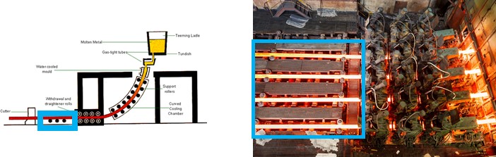
The presented work is part of a wider scope project (BEROA-GO). Among others, the different areas of a specific steelmaking process (SIDENOR, Olabarria steel mill) are analysed from the radiant heat recovery potential point of view. As a result, it is concluded that the section between continuous caster outlet and oxy-cutting has ideal conditions for radiant heat recovery, since it is an 8 meters long continuous casting line in which the steel is at a temperature of 1022 ºC at its hottest side and 890 ºC at the coldest [26].
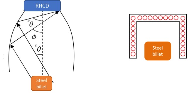
In this paper, the conceptual design of a radiant heat capturing device (RHCD) for continuous steel casting is presented, which would be located in the area shown in Figure 1.
To collect as much radiant heat emitted by the steel piece as possible, different design alternatives are analysed and compared, mainly focused on optical and thermal efficiency results. Although the application of the developed device is relevant in the steel industry, glass industry has been also proved to be potentially exploitable with a similar design [26].
Area in the steel mill between continuous caster outlet and oxy-cutting
When considering design alternatives to the mentioned RHCD, the maximization of radiant heat transferred is the main target, which in summary involves, the maximization of the view factor between the emitter (continuous steel piece) and the receiver (RHCD).
Radiative heat exchange between different surfaces depends on how each surface views the others and vice-versa, as well as on the radiative properties and the temperature of each surface. In the case that has been studied in this research, the radiation properties of the emitter and the RHCD (idealized as grey bodies), the emitter temperature and the design temperature for the RHCD are known and fixed. So, the only way of increasing the amount of energy captured by the RHCD is to modify the geometrical relationships between the different surfaces to improve how the emitter and the RHCD view each other. The parameter defined to measure the fraction of the energy leaving one surface which strikes the second directly (considering only geometric features, and not the properties and the temperature of the surfaces) is the view or configuration factor [27]. The view factor from one surface i to another surface j is denoted Fij. But to maximize the net energy flux that strikes the receiver area of the RHCD, a new factor , the configuration pseudo-factor, is calculated. The configuration pseudo-factor represents the fraction of the energy leaving one surface which strikes the second directly and via other surfaces. This factor depends not only on the geometry (view factors and areas) but also on the emissivity of all the surfaces that conform to the space where the radiative heat exchange is taking place.
That said, when approaching the different alternatives for the RHCD design, two different possibilities are studied: a solution including reflectors - which could be concentrators or collimators-, and a solution not including them. Each of these two possibilities offers a range of possible designs. So first, a qualitative assessment of the different possible designs in each solution has been carried out. Then, once the most appropriate design of each one is selected, a quantitative assessment based mainly on the calculation of the configuration pseudo-factor is performed to definitively select the best option.
It is noteworthy that, in all cases, the dimensional limitations of the continuous casting steel production process have been considered.
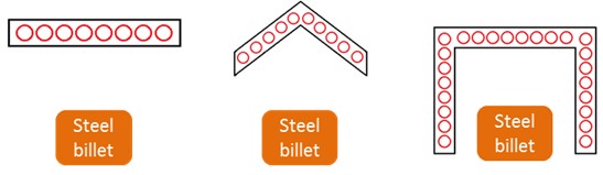
Figure 2 shows the transversal section of three different solutions for the analysed type of RHCD.
Transversal sections of different alternatives of RHCDs without reflectors
For the qualitative assessment of the different alternatives that arise for this type of RHCD, the following factors that have been considered:
-
RHCD surface: in this typology of designs, the configuration pseudo-factors are proportional to the capture surface of the RHCD surrounding the emitter. One way of increasing the value of the view factors is to enlarge the capture area. However, enlarging this area also increases energy losses; so depending on the scenario for the energy losses, this action may not be advantageous.
-
Complexity of the hydraulic circuit: the surface of the RHCD where the radiation emitted by the piece strikes will be cooled by a heat transfer fluid circulating through a specifically designed hydraulic circuit. The requirements for the design and integration of this circuit should be also considered. In Figure 2 the hypothetical hydraulic circuit is also shown (cross section of pipes).
-
Uniformity of the radiation reaching the RHCD: also refers to the previous factor since the more uniform the radiation, the simpler and more reliable the design of the hydraulic circuit. Unequal heating of the fluid could lead to detailed design problems associated with hot spots, etc.
-
Geometry simplicity: to get a qualitative estimation of the cost of the solution (the simpler the geometry, the lower the cost of the solution).
-
Process limitations: coming from the specific implementation of the solution at the introduction, and mainly related to restriction in the sizing of the RHCD.
According to all these factors, it is concluded that the “tunnel shape” solution (one at the right in Figure 2) is the best of the alternatives presented. The main strength of this solution is the conceptual higher area it provides. Thermal losses associated with this area can be easily minimized by including insulation at the external part, and in the internal part case (surface seeing the emitter), minimizing the unavoidable lateral opening between the emitter and the RHCD. This minimum value of the opening is a requirement imposed by the process, as well as the minimum distance between them. The resulting hydraulic circuit is not the simplest one due to the geometry; however, no important limitations are observed when thinking of a possible hydraulic circuit design. Several ideas arise for this design: tunnel shaped pipes connecting two main collectors at each side of the emitter, or longitudinal pipes connecting two U-shaped collectors at the front and rear part of the RHCD.
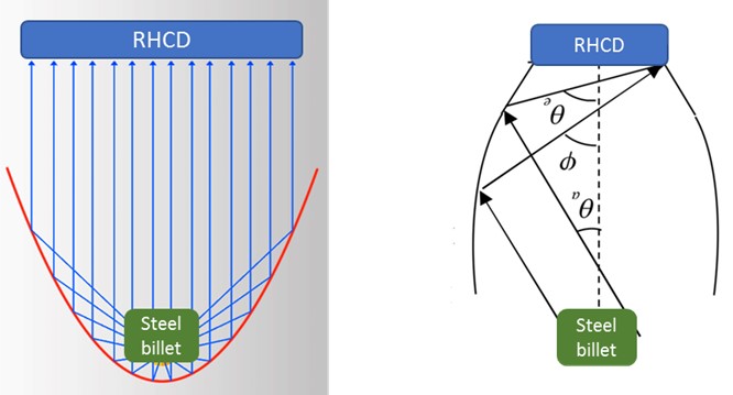
In this type of RHCDs, the energy per surface unit reaching the RHCD is increased by using reflectors so the radiation impacting the reflectors is mirrored to the RHCD. This strategy aims to decrease the heat losses of the RHCD to the ambient by reducing its area, maintaining at the same time the amount of radiant energy that coming from the piece strikes the RHCD. Two possibilities, collimators and concentrators, have been proposed depending on the location of the reflective surfaces. In both cases the objective is to reflect the energy emitted by the piece towards the RHCD, but in the case of collimators typically parabolic reflectors are located next to the piece and for concentrator case other geometries, such as the compound parabolic reflector, are located next to the RHCD (see Figure 3).
RHCD with collimator (left); RHCD with concentrator (right)
These solutions, when compared to those without reflectors, have the potential to achieve the same configuration pseudo-factors with lower RHCD areas, thus involving lower energy losses. In addition, these designs provide a more uniform radiation reaching the RHCD, which allows easier hydraulic circuit designs for the heat transfer fluid.
For the assessment of these new designs, apart from the factors already mentioned for alternatives without reflectors the following ones have also been considered:
-
Temperature at reflectors: temperature is an important factor to take into consideration since the shape and integrity of these elements highly depends on it, and a shape modification could involve a significant performance decrease.
-
Process dirt: the deposition of dirt (ever present in the industrial environment) on the surface of the mirrors entail a decrease in their reflectivity, so they would absorb more energy (increasing their temperature) while reducing the energy reaching the collector.
In fact, the real problem with collimators is that the reflective surfaces must be located very close to the emitter. This involves very high temperatures at these surfaces and interferences with other elements of the process (rolls, supports, etc.). Another important issue is the dirt deposition. Regarding the dirt particles, the collimator surfaces acts as a bowl and favouring these particles deposition.
Because of this, the use of collimators is therefore rejected in favour of the use of concentrators. Figure 4 shows different alternatives for concentrators.
Examples of concentrator types for the RHCD
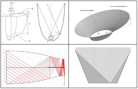
From them, the non-imaging concentrator called Compound Parabolic Collector (CPC)[28] was selected due to the combination of good performance and simple geometry.
As a summary, after the described work the study is focused on two different designs for the RHCD; a RHCD with CPC and a rectangular or tunnel shaped RHCD (see Figure 5).
A quantitative performance comparison analysis is carried out for both designs, focusing on both the power captured by the RHCD and the resulting efficiency. The analysis is carried out by means of the modelling and simulation of both designs, using Dymola® software for that purpose. Dymola® is a complete tool for modelling and simulating complex integrated systems for use in the aerospace, automotive, robotics and process sectors, as well as other applications [29].
RHCD with CPC system (left); Tunnel shaped RHCD (right)
In this way, the thermal balance of each surface is calculated considering the radiation exchange with the rest of the surfaces that make up each design (including the emitter and apertures), and thermal losses (convection) to the interior ambient.
The details of the models developed for both alternatives are explained below.
Model of the radiant heat capturing device with compound parabolic collector system. The modelling of this design in Dymola® is challenging since reflective surfaces introduce additional difficulties related to the number and direction of reflections, etc. and all the radiation exchange equations need to be programmed analytically by the user.
Sketch of the RHCD with CPC and its model representation in Dymola® software)
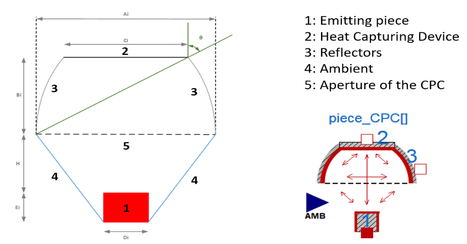
Because of that, the following assumptions have been made:
-
For the calculation of the view factors the system is treated as infinitely long. This means the energy loss through the edges of the system is neglected.
-
The ambient is considered as a black body: it absorbs all the energy reaching its surface while it also emits all its radiant energy due to its temperature.
-
The optical efficiency of the CPC is geometrically calculated (acceptance angle of the CPC) and then used to establish the amount of energy that once entering the aperture of the system (surface 5), finally reaches the RHCD (directly or indirectly). It has been assumed that energy that strikes the receiver has been reflected by the concentrator only once (there are in fact multiple reflections).
-
The radiation emitted by surface 1 and reflected by 3 that does not reach the RHCD, is considered lost to the ambient after a single reflection (also in this case there are in fact multiple reflections).
The radiation emitted by surface 2 (RHCD), reaching surface 3 (reflectors) is reflected diffusely. It is quite complex to calculate the behaviour of the concentrator when the source of radiation is the RHCD considering specular reflection and bibliographical sources do not have analytical expressions that can be used to describe it.
The last three assumptions have been introduced due to the impossibility of calculating the number of reflections that will take place within the CPC for the different cases (radiation emitted by the piece or by the RHCD). It will affect both the calculation of the heat absorbed by the reflectors and its temperature, and the calculation of the energy that strikes the RHCD area. Multiple reflections imply that the energy absorbed by the reflector will be higher and so its temperature.
These assumptions are necessary to carry out the proposed model, but they introduce a lot of uncertainty about the validity of the model results. Because of that, it is considered necessary to carry out the same analysis with other software to validate the mentioned simplifications. For that purpose, it has been decided to model and simulate the optical behaviour of the same design with Zemax® software. This tool calculates the percentage of radiation reaching each surface with respect to the radiation coming from an emitter (considering all possible routes), this is, the configuration pseudo-factor.
The method followed by Zemax® consists of simulating the trajectory of several rays, calculating their trajectory (reflections, etc.) individually. By simulating large number of rays emitted in all directions, a good approximation to reality is achieved. To provide a numerical result, the quantity of rays striking each surface is quantified and divided by the total number of rays emitted.
When introducing the CPC system in Zemax®, it has been tried to replicate the model from Dymola® as accurately as possible, so that the results are comparable. As the Dymola® model correspond to a 2D geometry (the system is considered infinitively long), Zemax® model covers a minimum space of the longitudinal axis, turning it into a 2D problem in practice. Thus, the radiation lost longitudinally by the open faces at the beginning and end of the receiver is neglected. Additionally, Zemax® model also includes the optical properties of each surface such as emissivity, absorptivity, reflectance, and type of reflectance, specular or diffuse.
An additional peculiarity of Zemax® software is that it does not allow for having more than one emitter at the same time, so two different Zemax® models have been developed: one where the piece is the only emitter, and another one where the RHCD is the only emitter. In Table 1 the parameters of the system used in all the cases are presented.
Model parameter values for the comparison between Dymola® and Zemax® models
|
Parameter |
Value |
|
Width of the aperture of the CPC, A[m] |
1.1 |
|
Angle of acceptance, θ[rad] |
π/4 |
|
Width of the piece, D[m] |
0.32 |
|
Height of the piece, C[m] |
0.22 |
|
Distance between piece and aperture, H[m] |
0-0.7 |
|
Emissivity of surface 1 at the temperature of the piece, ε1[-] |
1 |
|
Absorptivity of surface 1at the temperature of the piece, α1[-] |
1 |
|
Emissivity of surface 2 at the temperature of the RHCD, ε2[-] |
1 |
|
Absorptivity of surface 2 at the temperature of the RHCD, α2[-] |
1 |
|
Emissivity of surface 3 at the temperature of the reflector, ε3[-] |
0 |
|
Absorptivity of surface 3at the temperature of the piece, α3p[-] |
0 |
|
Absorptivity of surface 3 at the temperature of the RHCD, α3c[-] |
0 |
Figure 7 shows the result obtained with both Dymola® and Zemax® model simulations. Zemax® result is the one obtained when the piece is considered the only emitter and shows the percentage of radiation that reaches the RHCD. Dymola® result is calculated as the product of the view factor from the piece to the aperture of the CPC (F15) and the theoretical value for the optical efficiency of the concentrator. Both results are calculated for several values of the distance between the top of the steel billet and the CPC aperture (abscissa axis, in mm).
RHCD with CPC efficiency provided by both Zemax® and Dymola® simulations, depending on the distance between the piece and the aperture
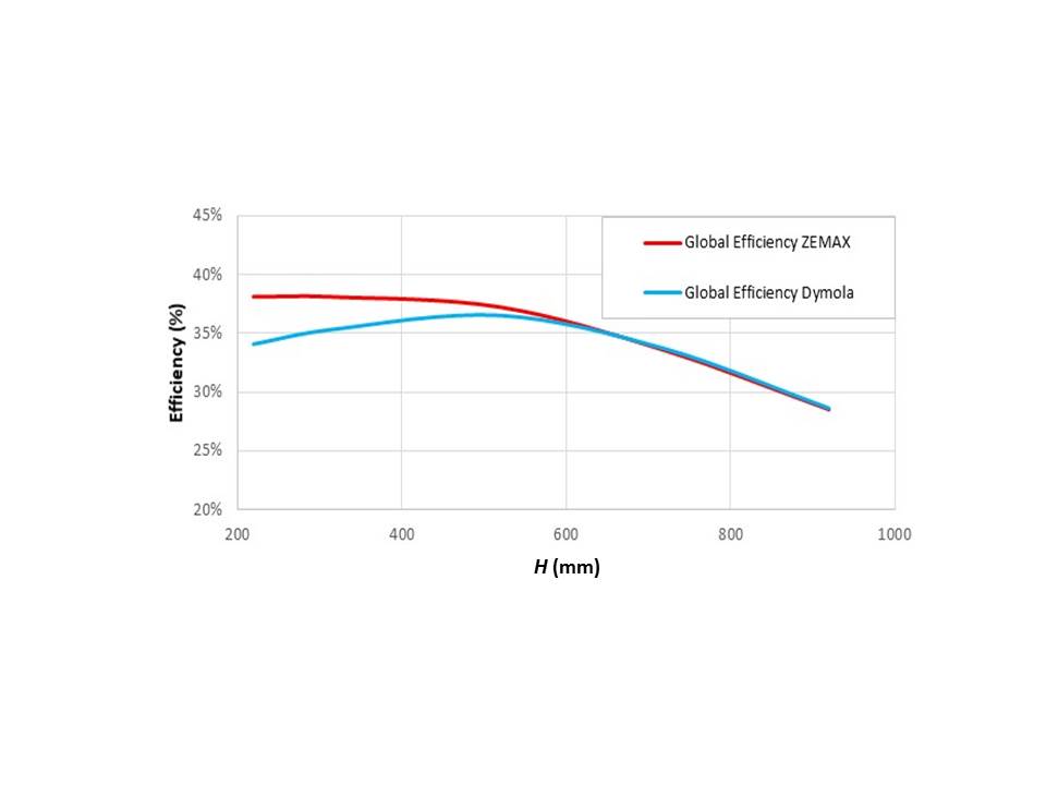
It can be observed that both results differ a little bit when the aperture of the CPC is close to the piece. This is because in the Dymola® model one of the considered assumptions was that the radiation that after passing the aperture does not reach the RHCD directly nor indirectly, goes to the ambient. This is not true since part of that radiation will return to the piece, and that quantity will be higher the closer the aperture and the piece are. However, Zemax® software, as it is a ray tracer, does consider the rays that return to the piece.
Once this error has been detected, it has been corrected in Dymola model and the new obtained results is represented in Figure 8. There, it can be observed that the error has been considerably reduced.
RHCD with CPC efficiency provided by both Zemax® and Dymola® simulations (including the corrected one), depending on the distance between the piece and the aperture
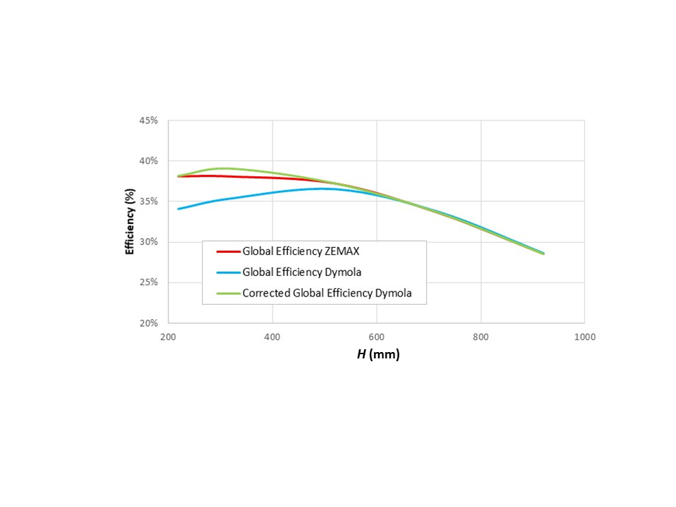
The small remaining difference is due to the approximation done in Zemax® model to emulate a 2D system. Thus, it is confirmed that the results obtained with both models are in good agreement.
On the other hand, Figure 9 shows the same type of result but this time comparing the case where the RHCD is considered the only emitter. Zemax® result represents the percentage of rays emitted from the RHCD that arrive at the piece by any way. To allow an appropriate comparison, the Dymola® model has been modified to simulate that the piece does not emit energy, and this has been done by setting the temperature of the piece to 0K, which cancels the radiation emitted by its surface.
In Dymola® the concentrators are treated as diffuse reflectors. In Zemax® two cases have been considered, one with specular reflection and the other with diffuse reflection at the reflectors. This way, on the one hand, the models of Dymola® and Zemax® can be compared (both with diffuse reflection), and, on the other, the effect of the simplification of considering all the reflection as completely diffuse can be seen.
RHCD with CPC efficiency provided by both Zemax® (RHCD as the only emitter, specular and diffuse reflections) and Dymola® simulation
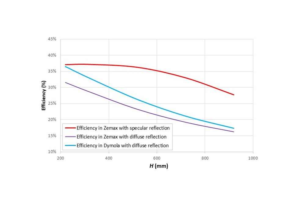
The efficiency has been calculated as the amount of energy reaching the piece out of all the energy emitted by the RHCD. In Figure 9 it can be seen that, for the case where the reflection of the mirrors is diffuse, the results of the models in Dymola® and Zemax® do not differ much, this difference being smaller as the distance between the piece and the opening of the CPC increases. The difference between both models is due to the calculation of the view factors in the Dymola® model, treating the system as infinitely long.
On the other hand, there is a great difference when considering the reflection to be totally diffuse or totally specular. Therefore, when the reflection is specular, most of the radiation emitted by the receiver and reflected by the mirrors, will end up coming out through the aperture after one or more reflections. Then most of this energy will end up in the piece. However, considering mirrors as diffuse reflectors, part of the energy reflected by these surfaces will return to the receiver instead of to the piece, making the efficiency in these cases to be smaller.
Figure 9 also shows how, as the distance between the aperture and the piece (H) increases, the efficiency in the case of specular reflection decreases. The reason for this is that as the distance increases, less of the reflected rays are reflected towards the piece. The same happens when considering the mirrors as diffuse reflectors, but to a lesser extent. Therefore, the difference in the efficiency is smaller at greater distances.
The results show how the models on both software give a very similar answer when the only emitter is the piece. However, there is a big difference between the results when considering in Zemax® specular reflection (this is the most real case).
When comparing both situations (piece as emitter and RHCD as emitter), the energy emitted by the piece is much higher. Therefore, the influence of the error in considering the reflection as diffuse in Dymola® is considerably lower than the values shown in Figure 9.
In conclusion, although the model built in Dymola® contains a non-negligible error related to the diffuse reflection assumption, this model can be used for a first comparison between the tunnel shaped RHCD and the RHCD with CPC system.
Model of the Tunnel shaped collector. The tunnel shaped RHCD is geometrically simpler and thus easier to model. Therefore, in this case, it has been considered not necessary to use a specific software such as Zemax® to contrast the validity of the assumptions considered.
However, and according to what has been mentioned so far, one of the most critical parameters in heat transfer by radiation is the view factor, so the first step has been to ensure that its calculation was correct. To do this, the calculation method has been implemented in two different software: Excel® and EES® (Engineering Equation Solver). Both methods have been developed and the results obtained have been cross validated.
The calculation method considers the three dimensions of the RHCD for the calculation of the view factors (as opposed to CPC, whose vision factor was calculated in 2D due to the complexity of its geometry). The strategy used has been to divide the system into simpler parts (shown in Figure 10), where the view factors between those parts are given by known analytical equations [3]. These equations are the view factors between two parallel or perpendicular flat surfaces.
Tunnel shaped RHCD surface selection for the calculation of the view factorsg
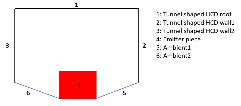
Once the individual view factors between the different surfaces have been calculated, a system is formed, and the calculation of the global view factor is carried out using the different existing properties and calculation methods for view factors [30].
Then, the cross-checked analytical expressions for the calculation of the view factors have been implemented in Dymola®. It has been modelled so the view factor value depends on the geometry and location of the piece and the RHCD.
Once equations of the view factors have been developed, the next step has been to implement the heat transfer through radiation equations. In contrast with case of the CPC, the only assumption considered has been that the ambient is treated as a black body.
Once the models have been worked out the corresponding simulations are carried out to obtain and compare the results. Figure 11 shows the developed simulation scenario for both described models.
Model of the experiment for the comparison of the RHCD with CPC system and the tunnel shaped RHCD
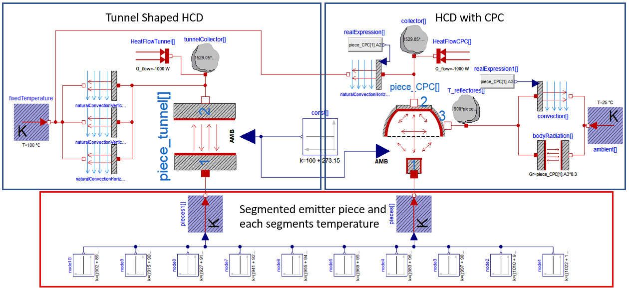
In these scenarios the emitter piece has been segmented in 10 pieces as the temperature at the entrance and exit of the piece in the continuous casting is different (the piece gets cooler along its route). In both cases, the tunnel and the CPC designs, heat losses to the ambient have been considered. The parameter values used for the simulation are presented in Table 2.
Parameters used during the experiment for the comparison of RHCD with the CPC system and the tunnel shaped RHCD
|
Parameter |
Value |
|
Temperature of the emitter piece, T1[K] |
1295.15-1163.15 |
|
Temperature of the external ambient, Tamb[K] |
297.15 |
|
Temperature of the internal ambient, Tamb_int[K] |
373.15 |
|
Temperatures required of the RHCD, T2[K] |
573.15–673.15–773.15 |
|
Length of the system, L[m] |
8 |
|
Emissivity of the piece at its temperature, ε1[-] |
0.8 |
|
Absorptivity of the piece at its temperature, α1[-] |
0.8 |
|
Width of the piece, D [m] |
0.32 |
|
Height of the piece, C[m] |
0.22 |
|
Emissivity of the tunnel at its temperature, ε2[-] |
0.96687 |
|
Absorptivity of the tunnel at its temperature, α2[-] |
0.9664 |
|
Width of the tunnel, A[m] |
0.56 |
|
Height of the tunnel, B[m] |
0.43 |
|
Emissivity of the RHCD at its temperature, ε2[-] |
0.96687 |
|
Absorptivity of the RHCD at its temperature, α2[-] |
0.9664 |
|
Emissivity of the CPC at its temperature, ε3[-] |
0.14485 |
|
Absorptivity of the CPC at the temperature of the piece, α3p[-] |
0.12205 |
|
Absorptivity of the CPC at the temperature of the RHCD, α3c[-] |
0.13529 |
|
Width of the aperture of the CPC, A[m] |
0.56 |
|
Distance between piece and aperture, H[m] |
0 |
|
Angle of acceptance, θ[rad] |
5π/12 |
The simulation considers a fixed temperature value of the RHCD, and three different temperature values have been tested: 573.15 K, 673.15 K and 773.15 K. In Table 3 the results from the three cases are presented.
Efficiency and absorbed power depending on the required temperature of the RHCD
|
Tunnel Shaped RHCD |
RHCD with CPC system |
|||
|
Temperature of the RHCD [K] |
Efficiency [%] |
Power per collector surface unit [W/m2] |
Efficiency [%] |
Power per collector surface unit [W/m2] |
|
573.15 |
72 |
40300 |
40 |
58750 |
|
673.15 |
66 |
37200 |
37 |
53820 |
|
773.15 |
59 |
32700 |
32 |
46340 |
In Table 3 it is shown how the results obtained from the tunnel shaped RHCD are much better than with the CPC system. Although the value for the power is higher for the CPC, this is because the power per unit area is considered. When multiplying this value by the total area of each system (4.32 m2 for the CPC, opposed to 11.36 m2 for the tunnel), it shows that the total power reaching the tunnel shaped RHCD is higher than that reaching the RHCD with CPC.
In the last and future years new measures to exploit the waste heat energy from the industry have been encouraged. In this sense, BEROA-GO project presents the possibility of exploiting radiative waste heat generated at steel and glass industry processes. After confirming the exploitability of this waste heat in both sectors, it has been necessary to study the different alternatives to capture this energy in the most efficient way.
The present study shows the process that has been followed until obtaining a conceptual design of the best possible RHCD. After studying some alternatives, two have been selected as the potentially most feasible designs: RHCD with CPC and the tunnel shaped RHCD. To compare the performance of each design, the corresponding models have been developed in the simulation tool Dymola®. With the models finished, a simulation scenario has been worked out to compare the performance of both options. The conclusion of the simulation results has been that the tunnel shaped RHCD obtains better results in terms of both efficiency and absorbed power. It deserves to be highlighted that, for the selected location, the sizing of the CPC has been highly conditioned by the space limitations imposed by the process, and that means that the optical performance obtained is much lower than if there were no such restrictions.
Since the described research was performed, the presented conceptual design has been evolved and a detailed RHCD design has been developed, this including the detailed design of the hydraulic circuit, integration details for locating it at the steel mill, etc. After that, a laboratory-scale RHCD of the developed design has been manufactured, and nowadays is being tested in an ad-hoc test rig constructed at Tekniker facilities to replicate the continuous casting process and provide thermal oil at realistic pressure and temperature conditions to the RHCD.
At the same time, a geometry optimization method for the tunnel shaped RHCD has been developed. This method will be used to obtain the optimal geometry of the tunnel depending on the limitations of the industrial process where it would be implemented. This development is part of a RHCD concept that is currently patent-pending [31].
This work has been performed under BEROA-GO project (Waste Heat Collection from Solids for Efficient and Competitive Use), granted by the Basque Government (Spain), exp. KK-2017/00060.
- Archive: Consumption of energy (June 2017), https://ec.europa.eu/eurostat/,
- ,
Modelling the potential for industrial energy efficiency in IEA’s World Energy Outlook ,Energy Efficiency , Vol. 8 (1), 2015, https://doi.org/10.1007/s12053-014-9273-7 - , Estimating the global waste heat potential, Renewable and Sustainable Energy Reviews, 2016
- ,
Industrial waste heat: Estimation of the technically available resource in the EU per industrial sector, temperature level and country ,Applied Thermal Engineering , Vol. 138 , 2018, https://doi.org/10.1016/j.applthermaleng.2018.04.043 - ,
Experimental investigation on a flat heat pipe heat exchanger for waste heat recovery in steel industry ,Energy Procedia , Vol. 123 , 2017, https://doi.org/10.1016/j.egypro.2017.07.262 - ,
A review of waste heat recovery technologies towards molten slag in steel industry ,Applied Energy , Vol. 112 , 2013, https://doi.org/10.1016/j.apenergy.2013.02.019 - Loss and opportunities analysis. US Manufacturing and Mining. , 2004
- ,
Waste heat recovery technologies and applications ,Thermal Science and Engineering Progress , Vol. 6 , 2018, https://doi.org/10.1016/j.tsep.2018.04.017 - Demonstration of a Waste Heat Recovery System at a Steel Plant in India , 2014
- , Coke Plant Technologies, ThyssenKrupp Industrial Solutions AG(coke oven gas treatment), 2017
- , Application of Radial Heat Pipe to Heat Recovery of Flue Gas, Proceedings of the 2015 International Conference on Advanced Engineering Materials and Technology, 2015
- , Waste Heat Recovery Unit for Energy Intensive Industries Thermoelectricity Harvesting, 2020 IEEE 29th International Symposium on Industrial Electronics (ISIE), 2020
- , , 2019
- ,
Thermal energy recovery from high-temperature blast furnace slag particles ,International Communications in Heat and Mass Transfer , Vol. 69 , 2015, https://doi.org/10.1016/j.icheatmasstransfer.2015.10.013 - ,
Design and evaluation of a heat recuperator for steel slags ,Applied Thermal Engineering , Vol. 56 (1-2), 2013, https://doi.org/10.1016/j.applthermaleng.2013.03.019 - ,
Water-energy and GHG nexus assessment of alternative heat recovery options in industry: A case study on electric steelmaking in Europe ,Energy , Vol. 141 , 2017, https://doi.org/10.1016/j.energy.2017.09.043 - ,
Role of steel slags on biomass/carbon dioxide gasification integrated with recovery of high temperature heat ,Bioresource Technology , Vol. 223 , 2017, https://doi.org/10.1016/j.biortech.2016.10.028 - ,
Multiple-Criteria Decision Analysis and characterisation of phase change materials for waste heat recovery at high temperature for sustainable energy-intensive industry ,Materials and Design , Vol. 186 , 2020, https://doi.org/10.1016/j.matdes.2019.108215 - ,
Experimental and theoretical investigation on a radiative flat heat pipe heat exchanger ,Energy , Vol. 174 , 2019, https://doi.org/10.1016/j.energy.2019.03.027 - ,
Numerical analysis for the heat transfer behavior of steel ladle as the thermoelectric waste-heat source ,Catalysis Today , Vol. 318 , 2018, https://doi.org/10.1016/j.cattod.2017.10.038 - ,
Thermoelectric System Absorbing Waste Heat from a Steel Ladle ,Journal of Electronic Materials , Vol. 47 (6), 2018, https://doi.org/10.1007/s11664-018-6073-4 - ,
EAF Heat Recovery from Incident Radiation on Water-Cooled Panels Using a Thermophotovoltaic System: A Conceptual Study ,steel research international , Vol. 89 (4), 2018, https://doi.org/10.1002/srin.201700446 - ,
Thermodynamic analysis of thermophotovoltaic systems used in waste heat recovery systems: an application ,International Journal of Low-Carbon Technologies , Vol. 13 (1), 2018, https://doi.org/10.1093/ijlct/ctx019 - ,
Applicability of Thermophotovoltaic Technologies in the Iron and Steel Sectors ,Energy Technology , Vol. 6 (6), 2018, https://doi.org/10.1002/ente.201700607 - ,
Thermophotovoltaic applications in waste heat recovery systems: example of GaSb cell ,International Journal of Low-Carbon Technologies , Vol. 15 (2), 2020, https://doi.org/10.1093/ijlct/ctz049 - ,
Radiant waste heat recovery from steelmaking and glass industry ,E3S Web of Conferences , Vol. 116 , 2019, https://doi.org/10.1051/e3sconf/201911600029 - , , Fundamentals of Heat Transfer, 1987
- , Solar engineering of thermal processes, 3rd edition, Wiley, 2006
- DYMOLA Systems Engineering. Multi-Engineering Modelling and Simulation based on Modelica and FMI, https://www.3ds.com,
- A Catalogue of Radiation Heat Transfer. Configuration Factors, www.thermalradiation.net,
- , Heat Capturing Device, 2018