


Sustainable energy systems based on the deployment of intermittent renewable energy sources, namely wind energy and photovoltaics, depend on reliable energy storage technologies to mitigate grid imbalances and grid congestions [1]. Research showed that Adiabatic Compressed Air Energy Storage (ACAES) systems offer great potential for large-scale energy storage [2]. Other forms of electrical energy storage, such as batteries, or fuel cells, provide significantly less storage capacity and are rather suited for tasks such as voltage stabilization [3].
Worldwide, there are two realized Compressed Air Energy Storage (CAES) plants, both still in operation today. The first was built in Huntorf, Germany, in 1978, running a 290 MWel expander and two 60 MWel compressors. The second is located in McIntosh, Alabama, with a capacity of 110 MWel, declared commercial in 1991. These plants still depend on the combustion of natural gas since the stored pressurized air must be heated up in order to allow a conventional expander process [4].
ACAES systems additionally provide a heat storage concept to return the thermal energy obtained during the compression of air, increasing the electric storage cycle efficiency to values up to 70%. As no fuel is used in the ACAES cycle, the technology generates no CO2, potentially allowing countries to meet their CO2 targets more easily [5].
During the charging mode of an ACAES process, ambient air is compressed beyond 60 bar, cooled down in a heat exchanger and stored in a suitable reservoir. The thermal energy of the air, resulting from the compression process, is stored in a high temperature thermal energy material. During discharging mode, the cool and pressurized air is released from the reservoir, runs through the heat exchanger and subsequently enters the air turbine at high enthalpy values. This thermal storage cycle constitutes the difference between the CAES and the ACAES process.
The main components of ACAES plants are the compressor, the air turbine, the high temperature heat storage system and the reservoir to store the compressed ambient air in.
The latter implies large investments unless synergies are found [6]. Salt production in Austria produces large caverns which are able to hold pressures up to 100 bar, thus providing low cost pressurized air storage reservoirs [7].
The remaining components, i.e. compressor train, air turbine and high temperature heat exchanger present challenges in regard to design, construction methods and materials, to meet the demands of the high pressure and high temperature process. These components are the focus of the current research work. Concepts are available [8], yet the economic boundary conditions for storage technologies in Central Europe are evolving rapidly. For that reason it is currently very difficult to establish a clear business case for any storage technology [9].
In this paper the results of a one year long feasibility study, financed by the Austrian Research Promotion Agency (FFG) to determine the storage potential of Austria’s salt caverns will be presented [10]. The study contains designs of realisable ACAES Plants in Upper Austria between 10 and 50 MWel, applying a high Temperature Energy Storage (TES) system currently developed at the IET in Vienna [11]. This active TES system is based on a fluidized bed counter current heat exchanger using sand as secondary heat exchanging fluid (sandTES).
Furthermore, the influence on the ACAES process of state of the art thermal turbomachinery, which is able to provide a compressor discharge temperature of 400 °C, is compared to the benefits of thermal turbomachinery in development, which will provide a compressor discharge temperature of 600 °C. One objective was to find the ideal compressor and expander process in terms of the maximum storage efficiency while achieving the requirements of the electric energy market.
Using the dynamic process simulation software ENBIPRO [12] and the stationary process simulation software EBSILON®Professional, the ACAES processes were designed and the obtained results were cross-checked. The layout for a suitable sandTES heat exchanger was realized by a MATLAB-Tool developed at the IET in Vienna [13].
Thermodynamic analyses were used to determine the ideal process regarding the intercooling pressure and to show the influence of higher compressor outlet temperatures on the ACAES efficiency.
It could be shown that the overall storage potential of Austria’s salt caverns exceeds a total of 4 GWhel in the year 2030 and, assuming an adequate performance of the heat exchanger, that a 10 MWel ACAES Plant in Upper Austria is currently feasible using state of the art thermal turbomachinery which is able to provide a compressor discharge temperature of 400 °C. Although it is currently very difficult to establish a clear business case for any storage technology, the potential for a future ACAES application remains [14].
The purpose of the study was to determine the storage potential of Austria’s salt caverns considering the potential implementation of an ACAES plant into the salt producing area. The topics geology, turbomachinery, heat exchanging technology, overall system design and energy system-economic considerations were addressed by different partners of the project consortium, each partner being a specialist in the concerned field.
The project consortium partner A, a longstanding traditional salt mining company in Austria, whose geologists helped to answer fundamental questions regarding the mechanical stability and structure of the salt caverns, provided specific information about existing and scheduled caverns, both solution-mined and dry-mined. Using these data, a two-scenario-catalogue was created, indicating the potential storage volume in the year 2025 and 2030. This catalogue summarizes the information about the depth and volume of the caverns, the length and diameters of the connecting pipes, the permitted pressure levels as well as the locations and positions of the caverns relative to each other. The latter was especially interesting with regard to the potential combination of caverns, maximizing the available storage capacity. On the basis of this catalogue, the caverns were ranked with respect to the potential utilization for ACAES plants in the capacity range from 10 to 50 MWel.
The sealing of the caverns, the utilization of porous stratum as well as the restrictions by geological stability were considered during regular meetings. A dynamic pressure load, as an intrinsic characteristic of ACAES processes, demanded the clarification of manageable pressure fluctuation frequencies and amplitudes within the caverns. Lastly, the restrictions of existing Austrian mining laws were taken into account.
The compressor and turbine are the main components of an ACAES plant. Unfortunately no ACAES system was ever realized, so no realistic turbomachinery model for process simulations was available. In order to provide specific data for designing and modelling work in the process simulation software ENBIPRO [12] and EBSILON®Professional, available machinery properties were taken into account.
Existing compressor technology allows compressor outlet temperatures up to 400 °C [15]. In addition, ambitious scenarios implying possible compressor outlet temperatures of 600 °C were considered in this study.
According to the project consortium partner B, a global research institute specialised in turbomachinery, such compressor trains are currently being developed and could be market ready within 5 years, assuming the required investments are available.
To consider such components in the corresponding simulations, first design calculations were used to receive the needed characteristic variables. Applying methods from relevant literature [16], a geometric design was found, satisfying the boundary conditions given by the inlet parameters, the outlet parameters and the compressor power at a certain isentropic efficiency. Using this design, a characteristic diagram of the compressor could be derived and subsequently implemented in the simulation, ensuring a dynamic model around a certain operating point.
Regarding comparable processes in the industry and using simplified static process simulations, fundamental requirements for air turbines used in ACAES plants were analysed. During meetings with project consortium partner B, information about the feasible operational behaviour, the controlling and the state of the art of suitable air turbines could be gained.
Thermodynamic and economic limitations lead to terminal temperature differences in any heat exchanger. Due to inevitable thermal losses to the ambiance, an ideal adiabatic process is never feasible, thus increasing the temperature difference of the air leaving the compressor during charging mode and entering the turbine during discharging mode. Nevertheless, the term “Adiabatic CAES” is used in literature, describing the thermal storage cycle which constitutes the difference to the CAES process.
Only a highly efficient heat exchanger system will make an ACAES electrical round-trip-efficiency up to 70% possible [5]. This heat exchanger efficiency is represented by the temperature difference of the working fluid between charging and discharging mode at minimal auxiliary power. Furthermore the dynamic behaviour of the heat exchanger has to meet the requirements of the ACAES process respectively the requirements of the targeted energy market.
To meet these requirements, a new type of active fluidized bed counter current heat exchanger system, using sand or fine powders as secondary heat exchanger fluid, is being developed at the IET in Vienna [11]. Numerous experiments showed that the transport of fine powders in a desired direction is feasible and the developed distributor and level control mechanisms allow a very flexible and dynamic flow control through the fluidized bed heat exchanger at minimal auxiliary power [15]. In addition to experimental work, the so called “sandTES” heat exchanger behaviour was simulated by a MATLAB-Tool developed at the IET in Vienna [13] and the particle suspension of the storage powder was simulated using the cpfd-simulation software Barracuda® [15]. These simulations allow the suitable design of a heat exchanger, meeting the boundary conditions given by the required heat rate, the primary and secondary material properties as well as the required temperatures of these materials at the inlet and outlet of the heat exchanger. At the same time, the heat storage capacity of the sandTES system is only limited by the construction restrictions for high temperature bunkers and solids handling systems required for storing the TES powder material.
The overall system design of an ACAES plant includes the technical design, the process design, the plant arrangement on site as well as the applicability for targeted energy markets, while simultaneously meeting the targets of the economic concept.
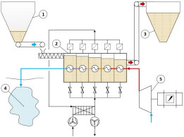
The main components of the technical design are shown in Figure 1 and Figure 2. During charging mode of the plant, an electric motor, provided with electric energy by the local grid, drives a compressor to compress air. The compressed hot air runs through the tube bundle of the sandTES heat exchanger where fine powdered fluidized sand flows in a counter current way over the tube bundle surface, transferring the thermal energy from air to sand. The TES material is stored in two large bunkers, defining the heat storage capacity of the sandTES system. Chain conveyors are used to transport the TES material between heat exchanger and bunkers. The cooled pressurized air is stored in a cavern and pressure variation combined with cavern volume, define the storage capacity.
ACAES charging mode: Cold silo (1); sandTES heat exchanger (2); hot silo (3); cavern (4); compressor (5)
ACAES discharging mode: Cold silo (1); sandTES heat exchanger (2); hot silo (3); cavern (4); turbine (5)
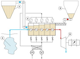
In discharge mode the process is run in opposite direction. Hot pressurized air drives the air turbine which itself runs a generator, feeding electric energy back into the grid.
To find the ideal process design of an ACAES cycle, the principle thermodynamic correlations were analysed, investigating the ideal number of intercooling steps as well as the ideal intercooling pressure level to minimize the compressor work and to maximize the storage efficiency, eq. (1). The thermodynamic correlations used for these analyses, are based on the equations for the isentropic change of state during the expansion, eq. (2), and compression, eq. (3), for an ideal gas. The analysis of ideal gas behaviour are justified, since the dependencies of the storage efficiency of intercooling steps, intercooling pressure level and compressor outlet temperature, is exactly the same as for non-ideal air. The non-ideal behaviour of air is taken into account by the utilised simulation software and the modelling results are presented in this manuscript:
Three potential salt mining sites were chosen, where site accessibility for construction work, settlement conditions, existing tunnel systems to the caverns and tunnel systems in between the caverns were evaluated. Besides the geographical and geological conditions, the developed electrical grid including transmission capacity of power lines and existing transformer stations were documented in order to evaluate the possibility of ACAES plants in the capacity range from 10 to 50 MWel.
The economic boundary conditions for storage technologies in Central Europe are evolving rapidly [9]. For that reason it is currently very difficult to establish a clear business case for any storage technology. As an example, the long term situation of the last decades with a big peak around midday, has disappeared on days with high PV production. As a consequence, there can be two peaks per day but with smaller difference in overall power volume. The price spread between peak and off peak period has sunk over the last years. This in conjunction with rapidly changing numbers both for prices and production and consumption profiles, makes it very difficult to establish a business case.
Nevertheless, specific cost estimations for initial investments and round-trip efficiencies for a saline cavern ACAES (ScACAES) plant are presented. These two numbers allow to analyze the technology for any techno-economical setting.
Furthermore, Austrian spot market data has been used for a two-cycle-per-day operation, to derive approximations of annual revenues in different energy markets and combinations of energy markets applying generic market models [14], as data from balancing markets is rare and hard to come by.
Accessible spot market data was used to identify periods offering the highest price spreads to further estimate the potential revenues during the day.
Specific investment costs were estimated, considering that the existing caverns substantially lower the costs for storage reservoirs by 10 to 20% of the overall CAES plant installation costs [3].
Periodic pressure fluctuations around 20% were found to be uncritical regarding the geological stability of the salt caverns in the present case. Also, concerning pressure frequencies, two complete charging/discharging cycles per day were classified as harmless by the responsible project consortium partner. The pressure build-up-rate will not be restricted by the rock mechanics. However, at the preferred mining site due to the shortest connections to the caverns, the pressure level must not fall below 80% of the maximum pressure level in order to prevent a lowering of the surface ground level. Table 1 shows the potential combinations of single caverns, resulting in a higher accumulated storage capacity.
Potential combinations of single caverns
Caverns |
Available [year] |
Max. pressure [bar] |
Σ Vol [m3] |
Connection length [m] |
|---|---|---|---|---|
A2-A6-A9 |
2029 |
86 |
548,725 |
443 |
F36-F37-F40 |
2022 |
19 |
186,591 |
310 |
F32/33-F42 |
2015 |
26 |
284,832 |
150 |
B14-B16 |
2019 |
120 |
19,301 |
185 |
BI12-BI13 |
2030 |
51 |
252,480 |
146 |
BI15-BI16 |
2025 |
56 |
376,281 |
140 |
BI22-BI23 |
2024 |
53 |
174,872 |
150 |
BI40-BI41 |
2026 |
57 |
129,949 |
215 |
Table 2 shows part of the compiled cavern catalogue already taking the process design (with or without compressor intercooling) and the assumed achievable compressor outlet temperatures into account. The allowed pressure in the caverns determines the available storage volume at a certain storage process pressure. The electrical storage efficiency was simulated using the simulation software ENBIPRO [12] and EBSILON®Professional. It can be found that a larger storage capacity will result in a lower storage efficiency which is caused by the intercooling and will be explained later in detail.
Part of the compiled cavern catalogue (site A) including simulation results
Scenario |
Pressure difference [bar] |
Vol [m3] |
Cap. [MWhel] |
η storage [%] |
|---|---|---|---|---|
400 °C, 2025, no intercooling |
13.15 to 10.52 (Δp: 2.7) |
1,429,138 |
332.35 |
64.11 |
400 °C, 2025, intercooling |
39.89 to 31.91 (Δp: 7.98) |
957,715 |
879.58 |
63.89 |
400 °C, 2030, no intercooling |
13.15 to 10.52 (Δp: 2.7) |
1,888,801 |
439.24 |
64.11 |
400 °C, 2030, intercooling |
39.89 to 31.91 (Δp: 7.98) |
1,333,236 |
1,229.98 |
63.89 |
600 °C, 2025, no intercooling |
31.5 to 25.2 (Δp: 6.3) |
957,715 |
878.72 |
69.14 |
600 °C, 2025, intercooling |
62 to 49.6 (Δp: 12.4) |
794,184 |
1,605.12 |
68.38 |
600 °C, 2030, no intercooling |
31.5 to 25.2 (Δp: 6.3) |
1,417,378 |
1,300.47 |
69.14 |
600 °C, 2030, intercooling |
62 to 49.6 (Δp: 12.4) |
1,175,705 |
2,376.21 |
68.38 |
The sealing of caverns created after 1960 will be possible as pressure proof cement was used for the connections. The utilization of porous stratum would not be economic as the effort to dry them out would be too large. The impact of the Austrian mining laws, concerning the utilization of the caverns as storage reservoirs, could not be determined.
Industrial compressors at lower pressure level are already in use at the CAES plants in Huntorf and McIntosh. Their modularity and flexible structure makes it very likely that the technology can be adΔpted for ACAES plants.
For high pressure and high temperature compressors, a new design has to be developed, allied to high temperature technologies e.g. of steam turbines. In this study, a layout for a two stage radial flow compressor has been calculated [17].
Table 3 shows the characteristic parameters for a 30 MWel high pressure compressor.
Characteristic parameters for a 30 MWel high pressure compressor
Stage |
Power [MWel] |
rpm [r/min] |
p2/p1 |
Isentr. eff. [%] |
ϕ inlet [m] |
ϕ outlet [m] |
|
1 |
4 |
15,000 |
3.34 |
1.4 |
85% |
0.31 |
0.41 |
2 |
3.1 |
15,000 |
2.63 |
1.29 |
85% |
0.31 |
0.41 |
By the scaling of normalized characteristic maps, the map shown in Figure 3 could be derived for different pressure ratios. The design condition was defined at the maximum pressure in the cavern and constant rotations per minute. For operating points close to the design condition, interpolation between the characteristics is possible.
Normalised characteristic map of a compressor
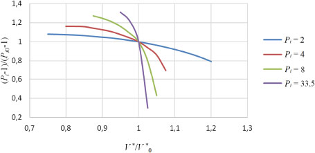
Different pressure ratios require an adaption of the compressor shaft speed in order to keep the compressor power at a constant level, which is demanded for the frequency control application. The most advantageous method is the control of the electric motor by a frequency converter.
Concepts of sliding pressure air turbines in a modular fashion are currently in development [5]. Part load operation should be possible with variable mass flow between 10 to 20% of the design mass flow. For high pressure expanders beyond 10 bar, axial steam turbine technology should be applicable. Low pressure turbines could be derived from radial turbo expander technology.
For maximum efficiency, the turbine should be able to adapt to a range of pressures and mass flows from the cavern as steam turbine control methods, like valve throttling, cause power losses. Therefore it is the aim to develop a sliding pressure air turbine including adΔptive stages for high pressures and temperatures.
Using the MATLAB design tool developed at the IET in Vienna [13], sandTES heat exchangers for different ScACAES plants in the cΔpacity range from 10 to 50 MWel have been designed. Table 4 shows the different design cases and the results regarding the construction dimensions.
Design cases of sandTES Heat Exchangers (HEX) and construction dimensions
ACAES-plant |
[MWel] |
10 |
10 |
10 |
30 |
50 |
50 |
Temperature difference |
[°C] |
46.3 |
50.8 |
49.7 |
51.5 |
46.3 |
45.9 |
Discharge time |
[MWhel/MWel] |
3 |
11 |
13 |
11 |
3 |
11 |
HEX width |
[m] |
5 |
7.6 |
7.6 |
11.1 |
12 |
12 |
HEX length |
[m] |
17 |
16 |
18 |
22,5 |
24 |
24 |
HEX inventory sand |
[t] |
92 |
113 |
114 |
416 |
672 |
672 |
HEX surface |
[m2] |
2,084 |
2,523 |
2,504 |
8,273 |
13,601 |
13,601 |
Bunker capacity sand |
[t] |
93 |
241 |
285 |
721 |
1,230 |
336 |
ηel,sandTES(*) |
[%] |
99.18 |
98.95 |
98.64 |
98.25 |
99.00 |
99.00 |
(*) The electrical efficiency of the sandTES heat exchanger is defined as:
The plant arrangement starts with the choice of advantageous caverns. At mining site B the connection length from the ground to the caverns and between the caverns are the shortest, minimizing the pressure losses of the air during charging and discharging. Furthermore the second largest volume through linking of two caverns is found at location B (see Table 1). The allowed maximum pressure is 55 bar, the allowed minimum pressure is 44.8 bar to prevent a lowering of the above ground level.
The caverns will be available in the year 2025. The connections are made of pressure proof cement and have a minimum inner diameter of 230 mm. Using both connections from the ground to the caverns, the flow cross-section is maximized. A 50 MWel ScACAES power plant will then result in an air velocity of about 25 m/s. The CAES plant in Huntorf permits maximal air velocities of 30 m/s. Higher power and thus higher air mass flow, results in an increase of pressure loss and subsequently in lower storage efficiencies.
The electrical infrastructure at location B is present with 110 kV power lines allowing transmission up to 300 MVA. Furthermore the location is fully developed, making a building permit more likely and the construction as well as maintenance easier.
Two types of compressors were applied in process simulations, allowing 400 °C and 600 °C compressor outlet temperatures. In both cases an isentropic efficiency of 85% was assumed. All assumptions regarding ambient parameters, geometric dimensions and engine efficiencies are listed in Table 5.
Technical designs of an ScACAES plant including results of process simulations
Power (motor, generator) |
[MWel] |
10 |
10 |
10 |
30 |
50 |
50 |
Storage capacity γ |
[h] |
3 |
11 |
13 |
11 |
11 |
3 |
Di connection |
[mm] |
2 × 228 |
2 × 228 |
2 × 228 |
2 × 228 |
2 × 228 |
2 × 228 |
Air velocity charge |
[m/s] |
4.91 |
3.79 |
3.76 |
10.56 |
15.83 |
18.33 |
Air velocity discharge |
[m/s] |
6.35 |
4.79 |
4.79 |
13.52 |
24.62 |
24.6 |
Pressure ambient |
[bar] |
1.013 |
1.013 |
1.013 |
1.013 |
1.013 |
1.013 |
Pressure comp, out |
[bar] |
44.37 |
45.61 |
45.93 |
48.28 |
53.65 |
47.4 |
Δp geodetic charge |
[bar] |
-1.38 |
-1.42 |
-1.64 |
-1.52 |
-1.64 |
-1.44 |
Δp geodetic discharge |
[bar] |
1.54 |
1.54 |
1.54 |
1.68 |
1.46 |
1.46 |
Δp pipe&HEX, charg. |
[bar] |
0.28 |
0.37 |
0.5 |
1.12 |
1.26 |
1.52 |
Δp pipe&HEX, disch. |
[bar] |
0.6 |
0.73 |
0.97 |
0.91 |
2.99 |
2.98 |
p, cavern max. |
[bar] |
45.47 |
46.64 |
47.07 |
50.16 |
54.03 |
47,32 |
p, cavern min. |
[bar] |
44.8 |
44.8 |
44.8 |
44.8 |
44.8 |
44.8 |
p, turbine, in |
[bar] |
42.65 |
42.53 |
42.29 |
46.54 |
40.35 |
40.36 |
T, ambient |
[°C] |
15 |
15 |
15 |
15 |
15 |
15 |
T, comp, out |
[°C] |
400.06 |
600.04 |
600.08 |
600.28 |
600.1 |
600.18 |
ΔT sandTES |
[°C] |
46.3 |
50.8 |
49.7 |
51.5 |
46.3 |
45.9 |
T, turbine, in |
[°C] |
353.76 |
549.37 |
550.38 |
548.78 |
553.71 |
554.28 |
T, turbine, out |
[°C] |
-4.97 |
85.49 |
85.51 |
81.46 |
91.46 |
91.72 |
p, intercooling 1 |
[bar] |
2 |
2 |
2 |
2 |
2 |
2 |
p, intercooling 2 |
[bar] |
3 |
- |
- |
- |
- |
- |
T, intercooling 1 |
[°C] |
16.5 |
59.4 |
59.15 |
54 |
43.2 |
55.5 |
T, intercooling 2 |
[°C] |
16.5 |
- |
- |
- |
- |
- |
Massflow compressor |
[kg/s] |
18.58 |
14.74 |
14.73 |
43.83 |
71.85 |
73.2 |
Massflow turbine |
[kg/s] |
27.89 |
21 |
21 |
61.78 |
105.27 |
105.19 |
T, cavern |
[°C] |
15 |
15 |
15 |
15 |
15 |
15 |
Volume cavern |
[m3] |
375,000 |
375,000 |
375,000 |
375,000 |
375,000 |
375,000 |
Charging time |
[h] |
4.51 |
15.74 |
18.61 |
15.56 |
16.18 |
4.33 |
Discharging time |
[h] |
3.00 |
11.05 |
13.03 |
11.03 |
11.04 |
3.02 |
ηs,compressor |
[%] |
85 |
85 |
85 |
85 |
85 |
85 |
ηs, turbine |
[%] |
88 |
88 |
88 |
88 |
88 |
88 |
ηel,motor |
[%] |
95 |
95 |
95 |
95 |
95 |
95 |
ηel,generator |
[%] |
98.56 |
98.56 |
98.56 |
98.56 |
98.56 |
98.56 |
ηmech,motor |
[%] |
99.8 |
99.8 |
99.8 |
99.8 |
99.8 |
99.8 |
ηmech,turbine |
[%] |
99 |
99 |
99 |
99 |
99 |
99 |
ηel.sandTES |
[%] |
99.18 |
98.95 |
98.64 |
98.25 |
99.00 |
99.00 |
ϰair |
[-] |
1.4 |
1.4 |
1.4 |
1.4 |
1.4 |
1.4 |
ηstorage |
[%] |
66.08 |
69.39 |
69.1 |
68.05 |
67.56 |
68.88 |
The overall electric cycle efficiency of an ACAES process is defined by the electrical, mechanical and isentropic efficiencies of the applied engines as well as by the ratio of the differences of enthalpy of the turbine to the differences of enthalpy of the compressor.
Thus, the optimization of the cycle efficiency requires the maximization of the turbine inlet parameters: temperature and pressure. The influence of the turbine inlet temperature on the achievable differences of enthalpy during the expansion is far greater than the influence of the turbine inlet pressure.
The turbine inlet temperature depends on the compressor outlet temperature and the temperature losses of the heat storage system. The turbine inlet temperature can be maximized by the optimization of the compressor and the heat exchanger.
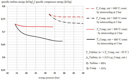
The turbine inlet pressure depends on the allowed pressure level inside the cavern but is also restricted by the icing temperature at the turbine outlet. Keeping in mind that the compressor outlet temperature is restricted by the compressor technology itself, one question was, whether intercooling during the compressor process, thus increasing the storage pressure and turbine inlet pressure, would lead to higher cycle efficiencies. It could be shown that any intercooling will subsequently reduce the overall electric cycle efficiency of an ACAES process. Figure 4 shows the ratio of the specific turbine energy to the specific compressor energy over the storage pressure, where the red and black lines represent constant compressor outlet temperatures achieved by according intercooling during the compressor process. The ratio is proportional to the cycle efficiency, assuming the charged mass of air is equal to the discharged mass of air. Furthermore it can be seen that a lower pressure level of intercooling reduces the negative effect of the intercooling on the cycle efficiency.
Ratio of specific turbine energy to specific compressor energy over storage pressure for different intercooling pressure levels, red: 2 bar, black: 5 bar
Spot market analyses show very small revenues for a two-cycle-per-day operation of an ACAES plant with assumed cycle efficiency of 70%, as listed in Table 6.
approximations of annual revenues derived from spot market data for a two-cycle-per-day operation (assumed cycle efficiency 70%) using generic market models
Year |
2011 |
2012 |
2013 |
2014 |
Average |
|---|---|---|---|---|---|
Revenue [EUR/MWel] |
~8,500 |
~14,000 |
~17,000 |
~12,000 |
~12,900 |
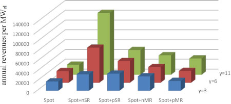
Using data from generic market models [14], annual revenues for an ACAES plant on different energy markets and combinations of energy markets were derived. Figure 5 shows that the combination of the spot market and the negative secondary control power (nSR) services market promises the highest profits. Bigger storage capacities γ (discharge time [h]) result in more independence from energy markets and leads to possible operation optimizations which itself increases revenues.
approximations of annual revenues for an ACAES plant on different energy markets and combinations of energy markets using generic market models (negative/positive secondary control power: nSR/pSR, negative/positive minute reserve: nMR/pMR). Assumed cycle efficiency 70%, assumed start-up time 5 min, storage capacities γ [h]
Referring to previous ACAES studies, applying the sandTES technology [15], leads to estimated specific investment costs of 1,600 EUR/kW. In this case the existing caverns substantially lower the costs for storage reservoirs by 10 to 20% of the overall CAES plant installation cost [3]. In comparison, the Sandia Report [3] gives specific initial investment costs of 1,200 USD/kW. This is for non-adiabatic systems, but nonetheless, the cost estimation of the present study, which was performed based on a conservative approach, arrives to comparable orders of magnitude and appears reasonable.
The overall goal of the ScACAES study to determine the storage potential of Austria’s salt caverns was achieved. It could be shown, that an accumulated cavern volume of 2.1 million m3 in 2030 implies a storage capacity of over 1.5 GWhel using 400 °C compressor technology and over 4 GWhel using 600 °C compressor technology.
Operational restrictions by geological conditions could be resolved and were considered in the technical design and process design of ScACAES plants.
Consistent with existing research, the need for fundamental development concerning turbomachinery was explained.
A novel type of a high temperature energy storage system currently developed at the IET in Vienna was introduced. This system called sandTES is based on a fluidized bed counter current heat exchanger using sand as secondary heat exchanging material. It was shown that applying this TES System, an overall electric cycle efficiency of an ACAES process up to 69% is possible.
Thermodynamic analyses were used to determine the ideal process regarding the intercooling pressure and to show the influence of higher compressor outlet temperatures on the ACAES efficiency.
Higher revenues of ACAES plants are only achievable by targeting combinations of energy markets through high operational dynamics and sufficient storage capacity.
Although the economic consideration of current market conditions promises low earnings, the potential for future ACAES applications remains.
Di |
inner diameter (pipe) |
[mm] |
p, Δp |
pressure, pressure difference |
[bar] |
Pi |
pressure ratio |
[-] |
Pi0 |
reference pressure ratio |
[-] |
T, ΔT |
temperature, temperature difference |
[°C] |
V * |
volume flow |
[m3/h] |
V *0 |
reference volume flow |
[m3/h] |
Δhs |
specific isentropic change of enthalpy |
[kJ/kg] |
Cp |
specific isobar heat capacity (air) |
[kJ/(kgK)] |
γ |
storage capacity |
[h] |
ηel |
electric efficiency |
[%] |
ηmech |
mechanical efficiency |
[%] |
ηs |
isentropic efficiency |
[%] |
ηstorage |
electric storage efficiency |
[%] |
ϰ |
isentropic coefficient (air) |
[-] |
-
REFERENCES
- ,
Energy Storage Needs in Interconnected Systems Using the Example of Germany and Austria ,Journal of Sustainable Development of Energy, Water and Environment Systems , Vol. Vol. 2 (Issue 3), :296-3082014, https://doi.org/10.13044/j.sdewes.2014.02.0024 - , , Compressed Air Energy Storage: Theory Resources and applications for Wind Power Energy Systems Analysis Group, 2008
- ,
Electricity Storage Handbook in Collaboration with NRECA ,Sandia Report, Sandia National Laboratories , 2013 - ,
A Review on Compressed Air Energy Storage: Basic Principles, Past Milestones and Recent Developments ,applied Energy , Vol. Vol. 170 , :250-2682016, https://doi.org/10.1016/j.apenergy.2016.02.108 - , Advanced Adiabatic Compressed Air Energy Storage for the Integration of Wind, European Wind Energy Conf, 2004
- ,
Adiabatic Compressed Air Energy Storage with Packed Bed Thermal Energy Storage ,applied Energy , Vol. Vol. 155 , :804-8152015, https://doi.org/10.1016/j.apenergy.2015.06.019 - ,
Compilation of Geological and Geotechnical Data of Worldwide Domal Salt Deposits and Domal Salt Cavern Fields ,Solution Mining Research Institute, EES International , 2014 - , Adiabatic Compressed Air Energy Storage for the Grid Integration of Wind Power, 2006
- ,
Feed-in Tariffs for Promotion of Energy Storage Technologies ,Energy Policy , Vol. Vol. 39 (Issue 3), :1410-14252011, https://doi.org/10.1016/j.enpol.2010.12.013 - ,
Current Developments and Examples of Sustainable Energy Technologies, Energy Innovation Austria, Austrian Federal Ministry for Transport ,Innovation and Technology, Climate and Energy Fund , Vol. Vol. 4 , :62015 - ,
sandTES – An Active Thermal Energy Storage System based on the Fluidization of Powders ,Proceedings of the SolarPACES 2013 International Conference , Vol. Vol. 49 , :983-9922014, https://doi.org/10.1016/j.egypro.2014.03.106 - ,
Stationary Design Calculation and Part Load and Dynamic Simulation as well as Validation of Energy Conversion and Power Plant Cycles ,VGB PowerTech , Vol. Vol. 89 (Issue 4), :82-882009 - , A Simulation Tool for a Thermal Energy Storage based on Sand, M.Sc. Thesis, 2011
- ,
Development of a Generic Model for Operational Optimization of Energy Storage Systems for Techno Economical Evaluation of Stationary Storage applications (in German) ,Verlag Karl Maria Laufen , 2014 - ,
Sublake Electrical Energy Storage, Klima- und Energiefonds, Blue Globe Report Smart Energies #2 , 2014 - , , Fluid Mechanics and Thermodynamics of Turbomachinery, 2010
- ,
Design of a Turbomachinery System for an ACAES Plant (in German) ,TU-Wien , 2014