


Hydraulic power-trains and related hybrid drives have found numerous applications in those engineering problems requiring high power density and high torque such as: heavy construction machinery [1], heavy duty road vehicles for sanitation and waste removal [2], diesel engine-powered rail cars and locomotives [3], and wind turbine transmissions capable of maintaining constant generator speed regardless of wind variations [4]. Moreover, hybridization of road vehicles has been steadily increasing, because it is able to provide significant gains in fuel economy [5], and also to facilitate reductions in greenhouse gases emissions [6]. This may be a powerful motivator for increased acceptance of hybrid vehicles by a typical purchaser [7].
Due to the fact that hybrid power-trains in general consist of two or more different energy sources, many power-train topologies are currently being implemented. These may range from simpler ones, such as series and parallel hybrid drives, to the more complex series-parallel structures [8]. Depending on the type of energy storage system used, hybrid power-trains are typically categorized as Hybrid Electric (HE) or Hybrid Hydraulic (HH). The former type is typically encountered in personal transportation in so-called Hybrid Electric Vehicles (HEV) [9] featuring battery energy storage systems. The latter hydro-pneumatic energy storage systems are often used in Hybrid Hydraulic Vehicles (HHV) for municipal heavy-duty waste disposal or delivery purposes [2]. Hybrid power-trains comprising flywheel mechanical energy storage [10] or pneumatic energy storage [11] are much less common.
In the case of HH drives for vehicular applications, different topologies may be considered depending on the field of application [12]. As indicated by the study presented in [13], properly sized hydro-pneumatic energy storage (i.e. hydraulic accumulator) represents a key aspect of operation of a HHV propulsion system. Moreover, sufficiently detailed mathematical models of both the hydraulic accumulator [14] and hydraulic pump/motor units [15] are needed for accurate hydraulic drive energy flow and dynamic behaviour analyses. These models may then be used as a basis for the design of control strategies suitable for heavy-duty hybrid vehicle power-trains [16]. The aforementioned strategies may also be equipped with regenerative braking capabilities [17] and adaptation to varying hydraulic unit operating conditions [18]. For example, in vehicular applications, HH drives are subject to power cycles characterized by frequent “starting-and-stopping”. Therefore, high-magnitude regenerative braking action is needed in order to maximize the potential of energy recovery [17]. This may be particularly emphasized for commercial vehicles subject to specialized driving missions, such as city buses and waste collection trucks [10]. Since the high power density of hydraulic accumulators may facilitate notable kinetic energy recovery potential, their round trip efficiencies may reach up to 94% [10]. This is well above the round-trip efficiency of batteries currently used within HEV’s, whose round-tip efficiency is typically around 80% [19]. Furthermore, so-called mild HEV’s may be subject to notable battery degradation under frequent starting and stopping regimes, as well as due to operating temperature variations [20]. Thus, the recently shown fuel consumption reduction potential of HHV’s in personal transportation [21] may represent an additional incentive for their more widespread use.
The typically complex structure of hybrid power-train provides many design opportunities in terms of power-train topology selection, components sizing and energy management controls. All together these terms have influence on the power-train cost and efficiency [8]. The hydraulic drive analyzed in this work assumes a hydromotor or a pump unit coupled with a prime mover in the form of electric machine or an internal combustion engine. In order to find the optimal components and respective operational parameters of such HH transmission unit based on limited manufacturers’ data, a systematic hydraulic drive sizing and parameterization methodology needs to be derived. This model may then be used to provide insights into the hydraulic drive operation. One example of such an approach has been given in [22] for the case of heavy-duty excavator, which has been subsequently used for its energy efficiency optimization [23]. In order to achieve this, energy efficiency and power losses of the hydraulic drive need to be analyzed with respect to the input power, and expressed in the form of efficiency maps with respect to hydraulic fluid pressure and flow (speed) [1]. The polynomial approximations may be used to characterize the power losses, such as shown in reference [1]. Polynomial approximations of pump capacity with respect to specific pumping speed may also be utilized, as shown in [24]. Similar efficiency map-based approach has been employed in [4] to dimension and parameterize the hydrostatic transmission in order to achieve operation in the maximum efficiency region of the radial piston pump system.
Having this in mind, this paper proposes a novel approach to HH drive component sizing methodology based on the Willans† Line method [25]. This method has been previously successfully applied to electrical machine model scaling [26], and internal combustion engine re-sizing [27]. It is, therefore, adopted in this paper to develop a scalable mathematical model of a hydraulic pump (or motor) units, which may be found in HHV drive applications [10]. This scalable model would be able to predict hydraulics pump efficiency for different size which would be particularly useful for optimal hydraulic drive component sizing and parameterization studies. Moreover, such an approach may also be suitable for sizing and energy efficiency analysis of similar hydraulic power systems, such as pipeline-based pump-turbine reversible systems [24].
The paper is organized as follows. Section 2 describes the hydraulic unit (pump) model with model parameters taken from catalogue data, followed by the approximation based on Willans Line method. The proposed methodology is elaborated in detail and modified to suit the hydraulic unit model definition in Section 3. The final scalable hydraulic unit model is verified against catalogue data for different unit sizes and the method approximation error is analyzed in detail in Section 4. Concluding observations are given in Section 5.
This section presents a straightforward mathematical model of hydraulic pump power conversion from mechanical to hydraulic (pressure/flow) form, facilitated by the hydraulic drive pump unit.
In typical HHV applications, the main power is produced by internal combustion engine in the form of mechanical torque and rotational speed [28]. This input mechanical power (Pi) to the hydraulic unit is characterized by its mechanical torque (τ) and angular velocity (ω), as follows:
The corresponding hydraulic unit output power (Po) is given by fluid pressure (p) and volumetric flow (Q), as:
The ideal relation between fluid pressure and mechanical torque is described as [29]:
where D is pump displacement and Δp is pressure difference between unit input pressure p0 and output pressure p. Note that for open loop hydraulics systems, p0 is equal to the environment pressure (if the resistance in the return line can be neglected).
In the latter case, the pressure difference is equal to the unit output pressure Δp ≈ p. Note also that the unit displacement (D) is related to the unit volume (V) according to D = V/2π. The theoretical relationship between angular speed (ω) and volumetric flow (Qt) is given by [28]:
Figure 1 shows the schematic representation of a hydraulic pump unit model which includes two types of power losses. The first source of losses is related to the so-called hydro-mechanical effects, which include viscous friction losses, mechanical friction losses, and hydrodynamic losses. These losses may be represented by the hydro-mechanical efficiency coefficient (ηmt). The second source of losses is associated with volumetric losses which include internal and external leakage and compressibility losses [28]. These losses can be lumped together and represented as additional leakage flow (Ql), or, alternatively, as equivalent volumetric efficiency coefficient ηvol = (Qt – Ql)/Qt = Q/Qt [10]. Overall unit efficiency can than be represented as the product of hydro-mechanical and volumetric efficiency ηtot = ηmtηvol.
A schematic representation of hydraulic pump unit
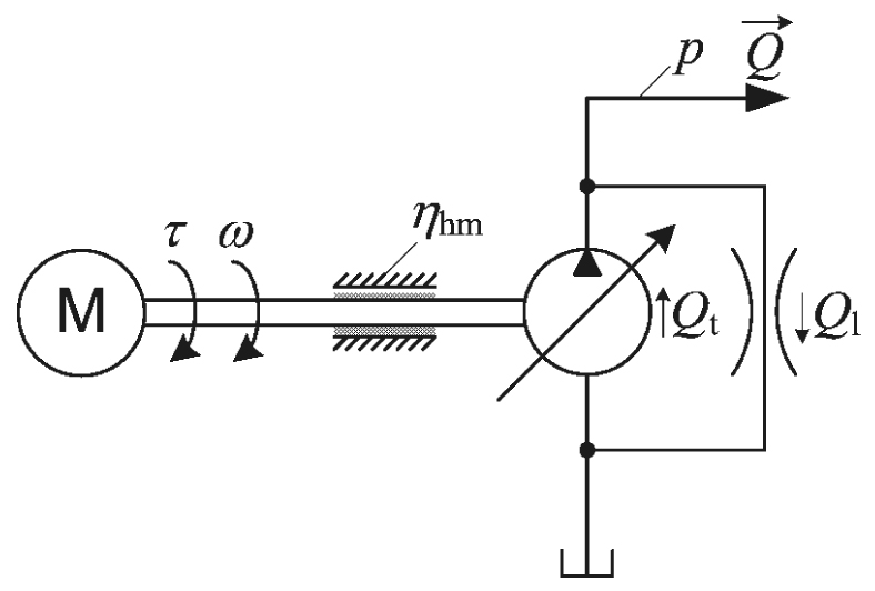
According to Figure 1, the effect of hydro-mechanical efficiency on the developed torque can be directly included into the torque vs. pressure relationship in the following manner:
using the relationship between angular speed (ω) and volumetric flow (Q) which takes into account the volumetric efficiency, which is given by:
Inserting eq. (5) and eq. (6) into eq. (1), yields the following power equation:
Typically, the HHV transmission consists of hydraulic axial piston units (pump and motors) in a so-called swash-plate or bent axis design [21]. After an exhaustive catalogue search, a Parker-Hannifin’s hydraulic variable displacement pump from P1 series [30] has been selected for this study as a representative example of the axial piston pump in the category of swash-plate design. The aforementioned P1 pump series can be ordered in 7 different sizes (corresponding 7 different displacement values), as shown in Table 1, and with power ratings starting with 30 kW for P1-018 model, up to 140 kW for P1-140 model.
P1 series type pump catalogue data
| Pump model | Pump displacement (D) [cm3/rev] | Max. working pressure (p) [bar] |
|---|---|---|
| P1-018 | 18 | |
| P1-028 | 28 | |
| P1-045 | 45 | |
| P1-060 | 60 | 350 |
| P1-075 | 75 | |
| P1-100 | 100 | |
| P1-140 | 140 |
Figure 2 shows the catalogue data and derived maps for the P1-160 pump unit and the case of maximum displacement. These data are used herein to illustrate the pump mechanical parameters, i.e., its total efficiency (ηtot) (Figure 2a), input power (Pi) (Figure 2b) and output flow (Q) (Figure 2c) with respect to pump pressure drop and driving axle rotational speed (n) [rpm]. Magenta-coloured ‘+’ markers in Figure 2 denote the catalogue data points, whereas the remaining map data are obtained by using cubic interpolation between data points. Catalogue [30] also provides the same data for each unit model.
P1-060 unit maximum displacement catalogue data for: overall efficiency (a); input power (b) and output flow (c)
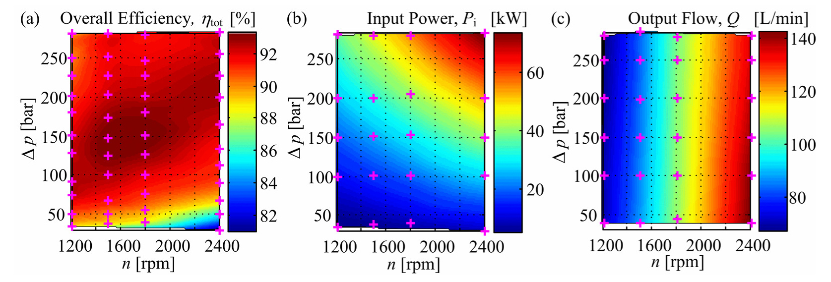
Based on eq. (1) and eq. (5), the pump hydro-mechanical efficiency map may be obtained from the input power map Pi(ω, Δp) as follows:
where the angular speed (ω) [rad/s] is obtained from rotational speed (n) [rpm] as follows:
Similarly, from the Figure 2c, and flow (Q) vs. speed (ω) relationship in eq. (6), the volumetric efficiency may be calculated as:
This section presents the hydraulic unit power losses approximation based on Willans Line method, and the resulting derivation of the scalable hydraulic unit model.
Willans Line rule has been applied in [25] to describe the relationship between the load and steam consumption for a turbine governed by means of throttling. Subsequently, the method has been extended to describe the energy conversion devices in hybrid electric and conventional vehicles, which included electric machines [26], and internal combustion engines [27]. In particular, [26] has proposed that this rule might be applicable to any power converting unit under stationary (steady-state) conditions in order to estimate its efficiency.
By definition, the Willans Line approximation for a power converter unit is represented as a straight line with line slope (k) which represents the internal energy conversion efficiency of the converter, and line offset (Pwl) which represents external (parasitic) losses [26]:
The total efficiency power converter is calculated from the relationship between the input and output power given by eq. (7), which yields after rearranging:
If all power losses are lumped together as a single loss source (Pl), then the output power is given by Po = Pi – Pl, and the total efficiency can be then expressed as:
Combining eq. (12) and eq. (13), yields the following relationship between the overall power losses (Pl), slope (k) and offset parameter (Pwl) as follows:
According to [31], the above overall power losses of the prime mover (i.e., electric or internal combustion motor) are described by a power losses map Pl(τ, ω), dependent on motor torque and speed. These losses are then approximated by a second-order torque vs. speed polynomial relationship as follows:
where c2(ω), c1(ω) and c0(ω) are angular speed-dependent coefficients of the above polynomial approximation. These coefficients are determined in [32] by means of convex optimization. This approach can be iteratively combined with the dynamic programming optimization algorithm, as shown in [33], in order to provide more precise estimates of approximation parameters values.
Even though the hydraulic unit power conversion process is typically defined by its efficiency [eq. (7)], an alternative approach based on overall power losses Pl(τ, ω) may also be used:
The power losses data points Pl(τ,ω) for a P1-060 hydraulic pump unit are represented by the map shown in Figure 3a, which has been derived from the overall unit efficiency map previously introduced in Figure 2a. Note that the unit efficiency map in Figure 2a has been presented in terms of rotational speed (n) and pressure drop (Δp), whereas the power losses map in Figure 3a is given in terms of angular speed (ω) and driving torque (τ). Hence, in order to equate the aforementioned maps, conversion from n to ω and Δp to τ needed to be carried out, taking into account the hydro-mechanical efficiency defined by eq. (8).
P1-060 hydraulic unit original: power losses map (a); approximation coefficients (b); approximation map (c) and approximation error (d)

For each angular velocity (ω) and torque (τ) value pair, proper values of coefficients c0, c1 and c2 of the second-order polynomial approximation in eq. (15) need to be found. This can be done by numerically solving a system of equations for each torque vs. speed data point, and the resulting maps of speed-dependent approximation coefficients are shown in Figure 3b. By using eq. (15) and coefficient values from Figure 3b, the power losses approximation map in Figure 3c is obtained. The resulting approximation percentile error (i.e., relative error between the original power losses map in Figure 3a and approximated map in Figure 3c) is presented in Figure 3d. It shows that the proposed approximation based on Willans Line is accurate within 5% over a wide range of hydraulic unit operating regimes.
In order to derive the rules for model up/down-scaling, and, thus, to achieve straightforward model scalability reported in the aforementioned references (see e.g. [32]), the scaling factor (sp) is introduced. This factor is defined as the ratio between original unit size which is used to derive coefficient values c0(ω)…c2(ω), and approximated unit size, wherein for hydraulic units, size directly corresponds to device displacement (D). Hence, the scaling factor is defined as:
where Dapp is approximated unit displacement and Dorig is original unit displacement.
Based on the above relationship, the scalable power losses (Pls) can be re-written as:
Since the input argument of the approximation polynomial in eq. (15) is the pump unit torque, while its coefficients are speed-dependent and do not depend on unit torque, the aforementioned scaling factor only refers to torque values as follows:
By combining eq. (19) and eq. (15), and inserting them into eq. (18), the following form of scalable polynomial approximation map is obtained [32]:
which, after multiplication with the scaling factor (sp) yields the following form of overall losses map relationship [32]:
This section presents the model scalability verification methodology, and related discussion of the proposed method approximation error.
For each hydraulic unit from the Parker-Hannifin’s P1 series, the power losses map Pl(τ,ω) is calculated first from the total unit efficiency map (Figure 2a) by using Pl= Pi(1 − ηtot) from eq. (13), while also taking into account the aforementioned relationships between rotational speed (n) and angular speed (ω) and between pressure drop (Δp) and output torque (τ). The resulting (i.e., converted) total efficiency map for P1-160 in τ vs. ω coordinate frame is presented in Figure 4a. This result has been accompanied by the speed-dependent approximation coefficient values c0(ω)…c2(ω), which have been determined from the power losses map (see discussion on Willans Line approximation above, and Figures 3a and 3b for P1-060 unit). To verify the accuracy of the approximation method, the scaled polynomial approximation in eq. (21) has been utilized with different values of polynomial approximation coefficients c0(ω)…c2(ω), and sizing coefficient (sp). The approximated power losses map, obtained by using eq. (13), is then converted to approximated total efficiency map, and the resulting difference between the original map and approximated is calculated.
P1-060 hydraulics unit: original efficiency map (a); approximated and scaled efficiency map (b) and approximation error (c)
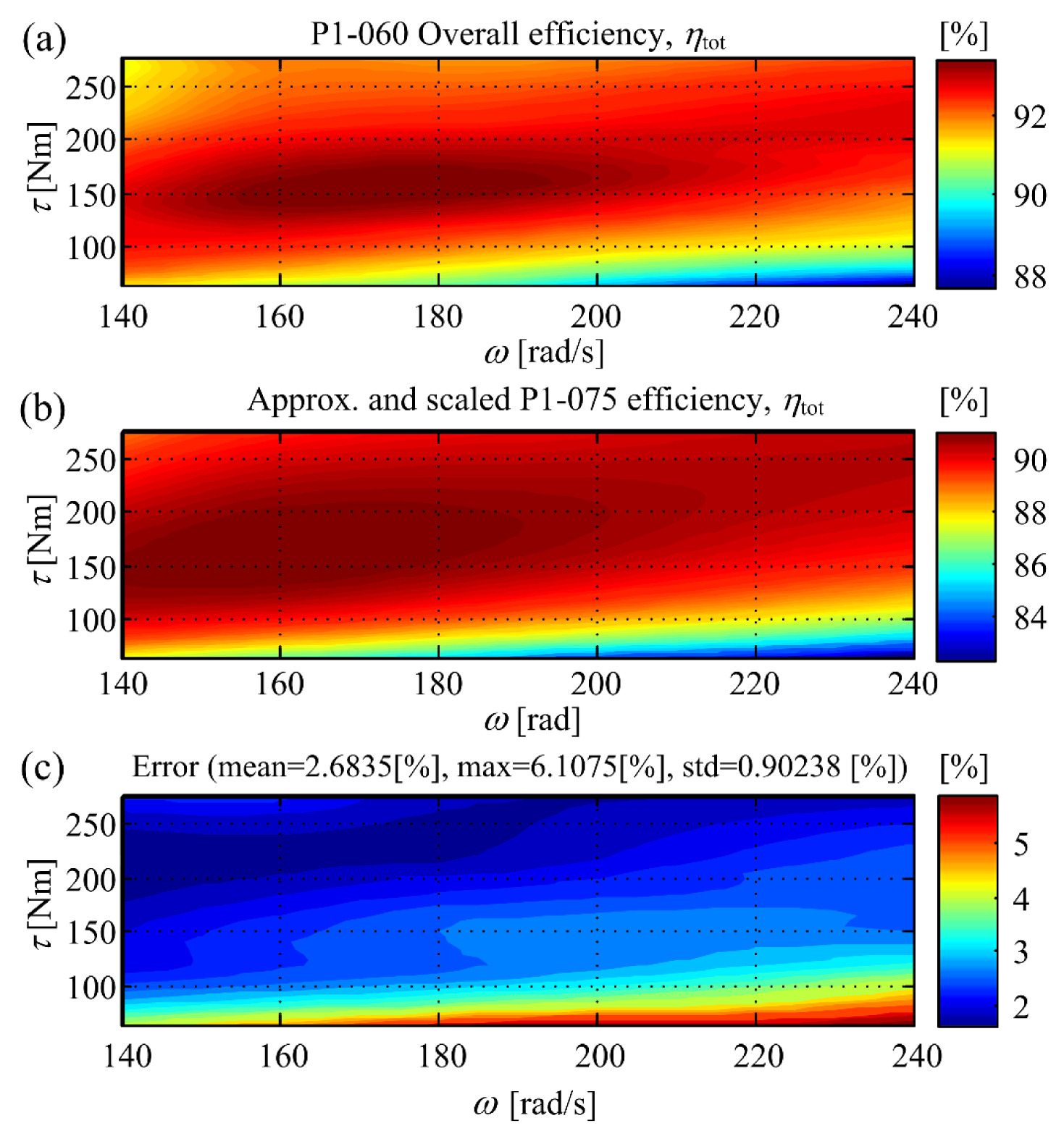
Figure 4 shows the comparison between the original P1-060 pump efficiencies obtained from the catalogue data (Figure 4a), and the approximate efficiency map shown in Figure 4b. The latter approximation is obtained by using approximation coefficients c0(ω)…c2(ω) obtained from the P1-075 pump unit data [30], and scaled down by the scaling factor sp= Dapp/Dorig = 60/75 = 0.8 [eq. (17)]. Figure 4c shows the relative difference (percentile error) between the original and approximated efficiency maps, as well as the mean error value, maximum error value and error standard deviation. The latter results point out to rather small approximation error bounds, which indicates that the approximation methodology based on Willans Line can predict the efficiency data values obtained from the manufacturer’s catalogue with very good accuracy.
In order to determine the overall model approximation accuracy, efficiency maps of all types of P1 units within the series have been compared, wherein the comparison has been performed between the catalogue efficiency data and scaled-model approximated efficiency data. The comparison results are shown in Figure 5 where Dorig represents displacement of hydraulic unit which has been used to define coefficients c0(ω)…c2(ω), while Dapp represents the unit displacement which has been used for the scaled approximation efficiency calculation for the purpose of comparison. Notably, the mean error plot in Figure 5a shows that the mean value of approximation error for all combinations is less than 5.5%. The maximum error plot in Figure 5b shows that for combination Dorig = 100 cm3/rev and Dapp = 75 cm3/rev the maximum error may reach up to 20%. However, this maximum error value refers to the boundary of the efficiency difference map (similar to the characteristic shown in Figure 4c).
Overall approximation errors: mean value (a); max value (b) and standard deviation (c)
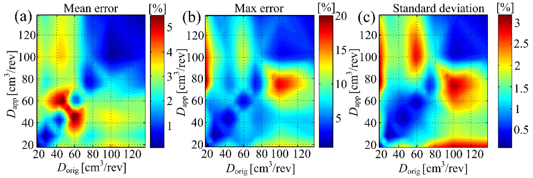
The paper has presented the scalable approximation of hydraulic unit (pump) efficiency model based on Willans Line method. The unit model parameters are taken from the manufacturer’s catalogue, and the resulting scalable hydraulic unit model has been verified against catalogue data for different unit sizes, and the approximation error of the proposed methodology has been analyzed by means of comparing the actual catalogue data and anticipated model-based data. For all considered combinations, the overall approximation mean error is less then 5.5%, and maximum error is always less then 20%, with largest absolute errors corresponding to the efficiency map data boundary curve.
Based on the presented results, the proposed approximation method has shown a clear potential to become a valuable tool for different component size efficiency assessment in hybrid hydraulic vehicles. It is anticipated that it would be particularly useful in those cases when efficiency maps of differently sized units are not available. In this respect, the proposed method might be a valuable aid in optimal hydraulic drive component sizing and parameterization studies.
Future work would be directed towards a more comprehensive assessment of Willans Line method based on a more detailed hydraulic pump unit efficiency data set compared to the basic catalogue data presented herein. Experimental verification of thus obtained efficiency map data may then be conducted on a target hydraulic pump/motor system. Finally, these results may be used as a basis for the development of a comprehensive simulation model of hybrid hydraulic vehicle power-train aimed at vehicle fuel/energy efficiency assessment for different power-train operating regimes.
It is gratefully acknowledged that the presented research has been conducted within the activities of the Centre of Research Excellence for Data Science and Cooperative Systems (DATACROSS) supported by the Ministry of Science, Education, and Sports of the Republic of Croatia. Authors would also like to express their appreciation of the efforts of the Associate Editor and anonymous reviewers whose comments and suggestions have helped to improve the quality of the presented subject matter.
- ,
Efficiency Improvement and Evaluation of Electric Hydraulic Excavator with Speed and Displacement Variable Pump ,Energy Conversion and Management , Vol. 150 , :62-712017, https://doi.org/10.1016/j.enconman.2017.08.010 - , Calculable Economy: Hydraulic Hybrid Drivetrain in Field Trial, 2009
- ,
Investigating an All-hydraulic Hybrid System for Diesel-hydraulic Rail Cars ,European Transport Research Review , Vol. 6 (2), :181-1892014, https://doi.org/10.1007/s12544-013-0121-1 - , Configuration Analysis and Design of a Wind Turbine with Hydrostatic Transmission System, Proceedings of the ASME 2016 International Mechanical Engineering Congress and Exposition (ASME-IMECE 2016), November 11-17, 2016
- , , Hybrid Vehicles and the Future of Personal Transportation, 2009
- ,
Modeling the Prospects of Plug-in Hybrid Electric Vehicles to Reduce CO2 Emissions ,Applied Energy , Vol. 88 (2), :2315-23232011, https://doi.org/10.1016/j.apenergy.2011.01.045 - ,
Policies for Promotion of Electric Vehicles and Factors Influencing Consumers’ Purchasing Decisions of Low Emission Vehicles ,Journal of Sustainable Development of Energy, Water and Environment Systems , Vol. 5 (2), :151-1622017, https://doi.org/10.13044/j.sdewes.d5.0139 - , , Vehicle Propulsion Systems ‒ Introduction to Modeling and Optimization, 2007
- ,
Energy Storage Systems for Transport and Grid Applications ,IEEE Transactions on Industrial Electronics , Vol. 57 (12), :3881-38952010, https://doi.org/10.1109/TIE.2010.2076414 - , Energy Efficient Hydraulic Hybrid Drives, Proceedings of the 11th Scandinavian International Conference on Fluid Power (SICFP’09), June 2-4, 2009
- , Investigation and Optimisation of Hybrid Electricity Storage Systems Based on Compressed Air and Supercapacitors, Ph.D. Thesis, 2006
- , An Overview of Energy Storage Systems Considering Renewable Energy Applications, Proceedings of the 6th Dubrovnik Conference on Sustainable Development of Energy, Water and Environment Systems (SDEWES 2011), 2011
- ,
Energy Storage Systems Sizing Study for a High-Altitude Wind Energy Application ,Energy , Vol. 76 , :91-1032014, https://doi.org/10.1016/j.energy.2014.04.001 - ,
Mathematical Modelling of a Hydraulic Accumulator for Hydraulic Hybrid Drives ,Mathematical and Computer Modelling of Dynamical Systems , Vol. 22 (5), :397-4112016, https://doi.org/10.1080/13873954.2016.1174716 - ,
Experimental Validation of an Analytical Model of Hydraulic Motor Operating under Variable Electrical Loads and Pressure Heads ,Applied Energy , Vol. 206 , :1309-13202017, https://doi.org/10.1016/j.apenergy.2017.10.010 - ,
Control Strategy of Hydraulic/electric Synergy System in Heavy Hybrid Vehicles ,Energy Conversion and Management , Vol. 52 (1), :668-6742011, https://doi.org/10.1016/j.enconman.2010.07.045 - ,
Design and Analysis of a Parallel Hydraulic – Pneumatic Regenerative Braking System for Heavy-duty Hybrid Vehicles ,Applied Energy , Vol. 225 , :60-772018, https://doi.org/10.1016/j.apenergy.2018.04.102 - ,
A Hydraulic Hybrid Propulsion Method for Automobiles with Self-adaptive System ,Energy , Vol. 114 , :683-6922016, https://doi.org/10.1016/j.energy.2016.08.042 - ,
Energy Efficiency Analysis of a Series Plug-in Hybrid Electric Bus with Different Energy Management Strategies and Battery Sizes ,Applied Energy , Vol. 111 , :1001-10092013, https://doi.org/10.1016/j.apenergy.2013.06.056 - ,
Synthesis and Experimental Validation of Battery Aging Test Profiles Based on Real-World Duty Cycles for 48-V Mild Hybrid Vehicles ,IEEE Transactions on Vehicular Technology , Vol. 66 (10), :8702-87092017, https://doi.org/10.1109/TVT.2017.2717187 - , Hydraulic and Pneumatic Hybrid Powertrain for Improved Fuel Economy in Vehicles, Alternative Fuels and Advanced Vehicle Technologies for Improved Environmental Performance, 2014
- ,
A Novel Hydraulic Excavator Boom Driving System with High Efficiency and Potential Energy Regeneration Capability ,Energy Conversion and Management , Vol. 166 , :308-3172018, https://doi.org/10.1016/j.enconman.2018.04.046 - ,
Energy Efficiency Analysis of Integrated Drive and Energy Recuperation System for Hydraulic Excavator Boom ,Energy Conversion and Management , Vol. 156 , :680-6872017, https://doi.org/10.1016/j.enconman.2017.11.074 - ,
Using a Statistical-Numerical Procedure for the Selection of Pumps running as Turbines to be applied in Water Pipelines: Study Cases ,Journal of Sustainable Development of Energy, Water and Environment Systems , Vol. 6 (2), :323-3402018, https://doi.org/10.13044/j.sdewes.d5.0181 - ,
Steam Turbines ‒Their Construction, Selection and Operation ,Proceedings of The South African Sugar Technologists’ Association , 113-1311966 - ,
Unified Modeling of Hybrid Electric Vehicle Drivetrains ,IEEE/ASME Transactions on Mechatronics , Vol. 4 (3), :246-2571999, https://doi.org/10.1109/3516.789683 - ,
Application of Willans Line Method for Internal Combustion Engines Scalability Towards the Design and Optimization of Eco-Innovation Solutions, SAE Technical Paper 2015-24-2397 , 2015, https://doi.org/10.4271/2015-24-2397 - , , Hydrostatic Transmissions and Actuators: Operation, Modelling and Applications, 2015
- , A Control-oriented Model of Hydrostatic Transmission with Application on Torque Vectoring Differential Modelling, Proceedings of 2008 ASME International Mechanical Engineering Congress and Exposition (IMECE 2008), 2008
- ,
Parker, P1/PD Series Medium Pressure Axial Piston Pumps, Variable Displacement, Catalog HY28-2665-01/P1/EN , 2014 - , On Optimization of Plug-in Hybrid Electric Vehicles, Ph.D. Thesis, 2012
- ,
Optimal Sizing of a Parallel PHEV Powertrain ,IEEE Transactions on Vehicular Technology , Vol. 62 (6), :2469-24802013, https://doi.org/10.1109/TVT.2013.2240326 - , An Iterative Dynamic Programming/convex Optimization Procedure for Optimal Sizing and Energy Management of PHEVs, Proceedings of the 19th IFAC World Congress, 2014