


While buildings are getting more heavily insulated and tightened for energy conservation, IAQ concerns and demand for fresh-air ventilation is increasing, resulting in higher sensible heating and cooling loads. Therefore, there is a dilemma between energy conservation and IAQ. ASHRAE Standard 62.1 [1] provides precise requirements about fresh air changes per hour for several building typologies and indoor functions, which put constraints on energy conservation measures. In this respect, Debacker et al. [2] analyzed the environmental footprint of ventilation in buildings, which is mandatory in Belgium since 199. They considered natural supply air and exhaust, natural supply and mechanical exhaust, and mechanically-controlled HRV. They applied Pareto optimality in carrying out LCA. Based on the First Law and environmental costs only, the HRV alternative offered the most preferable solution for the typical set of dwellings in Belgium. Ke and Yanming [3] carried out a similar study in China. They considered four climate zones in eight cities and investigated the applicability of HRV. Their metric of applicability was based on investment-specific cost and “energy” savings.
In simple terms, what an HRV unit does for energy savings and the economy is the sensible pre-heating of outdoor air in winter or sensible pre-cooling in summer with the exhaust air. The unit exergy of the thermal power gained from preheating or precooling, simply defined by the ideal Carnot cycle, is relatively small due to limited temperature rise or decrease in outdoor ventilating air. This exergy gain generally is not a match with the additional electrical exergy demand of the oversized or additional fans required for HRV operation in addition to the basic ventilation system requirements. Therefore, while an HRV unit may seem to be very efficient in terms of the First Law, often revealed by a high COP, it may prove to be inefficient according to the Second Law. Despite this exergy-based inefficiency, the design and analysis of HRV systems are based only on the First Law of Thermodynamics. To better describe the performance and environmental footprint of an HRV unit, an alternative performance factor, namely, COPEX, which is simply the thermal power exergy gained divided by all power exergy inputs attributable to the heat exchanging process involved for HRV. COPEX, which is less than one is a way to express exergy destructions. Therefore, exergy destructions leading to avoidable CO2 emissions may be minimized by letting COPEX value to approach one.
There is little research in the Second-Law aspect of HRV systems, while First-Law analyses are abundant. Likewise, Fouih et al. [4] investigated the adequacy of the HRV system in low “energy” buildings. They modeled an HRV unit using TRNSYS for dwellings in different climates of France and concluded that the adequacy of the HRV system depends on the building types, the heating loads, and the ventilation device characteristics. In their paper, Deymi-Dashtebayaz and Valipour-Namanla [5] investigated the thermodynamics (First Law only) and thermodynamic feasibility of recovering waste heat from the computer racks in a data center using an air-source HP in Mashad, Iran and using it for space heating purposes. They reported that the system financially pays itself in 2.5 years and also improves the PUE, ERF, and ERE of the data center [5]. Taha al-Zubaydi and Hong [6] experimentally investigated counter-flow HE for energy recovery ventilation in cooling mode in buildings [6]. They determined that dimpled surfaces perform about 50% better than flat surfaces.
In terms of the First Law again, HRV and EAHP are quite effective in a district energy system, especially in cold climates by raising the return temperatures to the district [7]. They compared the performance of a renovated building in a cold climate with HRV and three different EAHP connection configurations. The return temperature and energy use of the studied DH substations were modeled. The EAHP increased the weighted average return temperature of DH by 10 °C or 15 °C compared to HRV, depending on the connection scheme. The EAHP connection configurations had almost no effect on the seasonal COP of the HP, which was approximately 3.6 and corresponded to the measured best practice in the literature. Based on their simulations, they recommended the simplest EAHP connection scheme with the lowest DH return temperature. Cai et al. [8] have proposed to generate electric power through thermo-electric generators and then used it for refrigeration rather than keeping it as heat and utilize it as heat. They claimed that such a system has a large potential in the “energy”-efficient buildings. They, however, ignored that heat has relatively higher unit exergy than cold and thermo-electric cooling has low conversion efficiency. Therefore, it is better to utilize heat as heat.
Zhang et al. [9] have developed an Excel spreadsheet program to analyze and carry out a feasibility study of a residential energy recovery ventilator with a built-in energy economizer. They pointed out that a built-in economizer makes the system much better in cost recovery. In their paper, Zeng et al. [10] made a detailed review of the existing A-A heat and mass exchanger technologies for building applications. They carried out an extensive investigation about the heat and mass exchanger-integrated, energy-efficient systems for buildings, ranging from passive to mechanical ventilation systems, defrosting methods, and dehumidification systems. Their review concluded that HE results in insufficient airflow in passive buildings, HRV or ERV systems are responsible for additional pressure drops, air leakage, and noise in the ducts, defrosting problems in cold climates, and finally, ERV systems require additional heat in dehumidification and regeneration phases. Building energy use is closely linked with CO2 emissions, reported by many authors like Chenari et al. [11]. Their review showed that many factors must be taken into account for designing energy-efficient and healthy ventilation systems. They also concluded that utilizing hybrid ventilation with suitable control strategies leads to considerable energy savings, thus a reduction in CO2 emissions. According to the 2014 report from the IPCC, total anthropogenic GHG emissions have been continuing to increase over 1970 levels, despite a growing number of climate change mitigation policies. Annual GHG emissions grew by almost 1.0 G ton of CO2 by which 78% of emissions were from fossil fuel combustion. The built environment is responsible for about 40% of this portion [12]. In this respect, heat recovery systems in buildings have been represented as promising technologies by Cuce and Riffat [13] due to their capability of providing “considerable energy savings” in buildings. Yet they ignored the presence of avoidable exergy destructions in their analysis.
According to another study, by applying an energy recovery system to building HVAC systems, roughly up to 66% and 59% of sensible and latent energy can be recovered [14]. In a detailed monitoring study of a UK dwelling, the efficiency of the installed mechanical ventilation with heat recovery was found to be over 80% [15]. However, all these figures are based on the quantity of energy defined by the First Law. These studies do not account for rating and evaluating methods, beyond providing a thorough account of different technological details, except thermal efficiency, and NTU values. Several other researchers have concentrated only on topics like fan noise, low First Law efficiency, and leakage problems for de-centralized ventilation systems with a HE. According to these studies, decentralized ventilation is based on a single room or a small conditioned space, which has the potential of minimizing pressure losses due to the short travel distance of the air, when compared with centralized ventilation [16]. Manz et al. [17] have tested and simulated the performance of various types of decentralized ventilation units for cold temperate climates. Recently, several studies about decentralized ventilation units with heat recovery have been carried out focusing on cold, temperate, warm, and humid climates. Smith and Svendsen [18] have developed a short plastic rotary HE made of a polycarbonate honeycomb with small circular channels for single-room ventilation based on thermal design theory. Their experimental results demonstrated the potential of reducing heat recovery by slowing rotational speed, which is required to prevent frost accumulation. The same authors investigated the effect of a non-hygroscopic rotary HE on a single-room about its relative humidity. They also studied the sensitivity to influential parameters, such as infiltration rate, heat recovery, and indoor temperature [19]. Coydon et al. [20] have investigated several building facades, which are coupled with HRV systems, and showed that counter-flow type HE recovered 64% to 70% of heat. Again, all the research work cited above were based on the First Law.
There is quite a few exergy-based research about waste-heat recovery systems but they are concerned with the equipment components, without a holistic look for the exergy match between the supply and demand that needs to cover the wide range starting from the primary fuel input and ending at the final application through the waste HRV. Cuce and Riffat [13] further provided a detailed account for the exergy analysis of such equipment. Recently, exergy analysis of a cross-flow HE was performed by Kotcioglu et al. [21]. They have found that the HE efficiency decreases with the increasing air flow velocity. Yilmaz et al. [22] also presented an exergy-based performance assessment for HE. On the other hand, the exergy transfer effectiveness for HE has been described by Wu et al. [23]. These studies shed light on the exergy aspect of the waste heat recovery systems, yet they fall short of a holistic analysis of the overall performance and they exclude the relationship between exergy destructions and causing avoidable CO2 emissions. Furthermore, exergy and CO2 embodiments of the HRV construction material for LCA analyses were completely ignored. Despite certain shortcomings concerning the need for a holistic approach to the exergy performance of buildings in the literature, LowEX tool [24] that has been developed in the framework of Annex 37 by IEA ECBCS is an important step towards a better understanding of the importance of exergy analysis especially in low-exergy building applications, namely low-temperature space heating and high-temperature space cooling. However, this tool does not cover the avoidable CO2 emissions due to exergy destructions, according to the ‘Rational Exergy Management Model’, which can be as large as direct emissions in magnitude. Furthermore, it does not cover yet embodied exergy destructions, which are especially important for nZEB and nZEXB equipment such that their payback periods are quite long.
With the ever-increasing awareness of the importance of utilizing the waste heat in air-conditioning and ventilation systems in green buildings, A-A HE is becoming a vital component of nZEB and nZEXB cases. According to the EU Directive 2010/31/EU [25] on the energy performance of buildings (with the First Law of Thermodynamics), starting from the 31st December of 2020, all new buildings will be required to be nearly-zero energy buildings. EU has not yet realized the importance of the Second Law in the quest for decarbonization. Yet, Tronchin and Fabbri [26] have developed a new simplified method of evaluating the exergy of the energy consumed in buildings to find a relationship between the HVAC loads of buildings including envelope heat transfer and the energy conversion plant and its sub-systems like radiators. They argued that the exergy analysis of energy consumption in heating and cooling of buildings could be a tool to evaluate an exergy tariff to promote low-exergy HVAC plants. They further argued that such an exergy-based building performance tool based on Annex 37 may be utilized to evaluate the relationship between energy/exergy consumption: their new model evaluates the energy performance of buildings by establishing a direct relationship among exergy, temperature variations, and TOE. The originality of their model, which they name ‘Exergy Performance of Buildings’, emanates from the fact that their exergy-based model is structured on the energy-based EU Energy Performance in Buildings Directive. They compared the two approaches and concluded that the exergy-based model provides a more comprehensive analysis technique such that it reveals exergy destructions, which are not acknowledged by an energy analysis. HRV is a sub-system in their model and therefore it may be instrumental also for the HRV performance.
Among many different types and means of recovering heat from the exhaust air, fixed-plate heat recovery is a simple yet widely used technology. The structure of fixed-plate HE is based on several thin plates arranged together to separate internal airflows. The airflow between these plates create an additional pressure drop, namely P and thus lead to additional fan power demand in electrical form, namely E, that must be satisfied by either by fan oversizing or adding more fans. It must be remembered that E only relates to the HE of HRV over the ventilation system without heat recovery.
Regarding the airflow arrangement, there are three types of fixed-plate exchangers: counter-flow, cross-flow, and parallel flow [27]. The typical efficiency of fixed-plate heat recovery is in the range of 50-80% [27]. In the existing building stock, however, there is less than 1% of HRV in Europe [28]. According to the same publication, in new buildings, MEU still dominates the market, while the share of HRV units is increasing rapidly.
Figure 1, which is a reproduction from the ASHRAE Handbook-HVAC Systems and Equipment, shows the basic model for a fixed-plate, A-A type HRV unit. In this figure, the stand-alone HRV model considered as isolated from its surroundings and the additional/oversized fans and the power grid [29]. Even if such factors are included, they are limited to the quantity of energy recovered and spent by neglecting their different qualities. The unit exergy of thermal power gained or extracted (in cooling), εH is substantially lower than the unit exergy of electric power, εE which is virtually 1 W/W.
Air flows and DB temperatures in a stand-alone HRV [29]
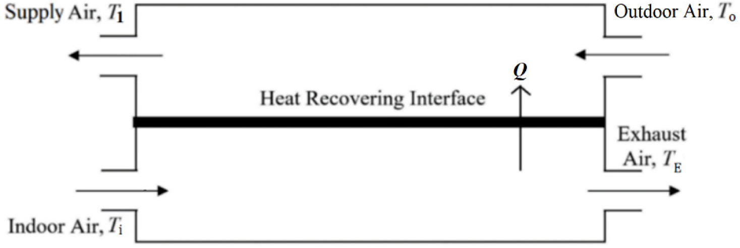
There is an exergy imbalance between them. Furthermore, Figure 1 does not question the origin of power generation and the fuel used. The fan power must be limited somehow for positive exergy gain from the exhaust air. The only ASHRAE source available, which deals with the limiting of fan power in air handling is the ASHRAE Standard 90.1 [30]. In Tables 6.5.6.1-1 and 6.5.3.1 of Standard 90.1 regarding the fan power limitations, the fan power is limited by a ratio of 1.2 BHP per 1,000 cfm (1.896 kW/m3s-1) for flow rates less than 20,000 cfm (9.44 m3s-1) and for the given US climate zone of 7, B. To give an example, consider Table 1, which reproduces an edited version of a typical data set from the commercial literature [31]. This stand-alone HRV unit reclaims 18.24 kW of heat, Q at an airflow rate, V of 0.83 m3/s.
Sample data for a commercial HRV unit [31]
| Specifications | HRV Product model number | ||
|---|---|---|---|
| 1 | 2 | 3 | |
| Air flow rate (V) [m3/s] | 0.83 | 1.11 | 1..38 |
| Thermal efficiency (ηI) | 0.65 | 0.51 | 0.46 |
| T1 [K] | 290.8 | 289.1 | 288.5 |
| Q [kW] | 18.24 | 22.00 | 26.47 |
| EXH = Q × (1 - T0/T1) [kW] | 1.116 | 1.225 | 1.422 |
| EXE, E = (εE ~ 1 W/W) [kW] | 2 × 0.65 | 2 × 0.80 | 2 × 0.95 |
| First Law COP = Q/E | 14.03 | 13.75 | 13.93 |
| Second-Law COPEX = EXH x (1 - 0.44 ηI)/E | 0.613** | 0.594** | 0.597** |
| Approximate weight (W) [kg] | 112 | 135 | 145 |
T0:Tref = 273 K*, Ti = 295 K, EXH = (1 - T0/T1) × Q. There are two fans. The total pressure is 360 Pa.
For an outdoor air temperature of 0 °C.
With 44% in-house use of peaking exergy.
The First Law efficiency (ηI) is 0.65. Outdoor air at 273 K is preheated to a temperature (T1) of 290.8 K. It requires 2 × 0.65 kW dedicated fans for heat recovering purpose in the HRV unit itself, apart from the basic ventilation system. According to the traditional COP definition, this HRV unit has a COP value of 14.03 [18.24 kW/(2 × 0.65 kW)]. This is a favorable value in terms of the First Law. If ASHRAE Standard 90.1, which permits a total fan power ratio of 1.896 kW/m3s-1 is applied to the first column of Table 1, 1.58 kW of fan power is permissible (1.896 kW/m3s-1 × 0.83 m3/s), which is above the 2 × 0.65 kW fan power, installed by the manufacturer. If the ASHRAE rule applies then COP and COPEX values would reduce to 11.5 and 0.50, respectively. From the Second Law perspective, the total permitted fan power needs to be conservatively less than 0.83 kW instead of 1.58 kW. This is only about half of what ASHRAE Standard 90.1 permits. ASHRAE Standard 90.1 does not refer to the Second Law at all and causes avoidable exergy destructions and thus more CO2 emissions, because CO2 emissions are proportional to exergy destructions [see eq. (25) in the following sections]. In this example, the supply air to the indoors needs to be temperature peaked by 6.2 K to raise it to a temperature of 299 K at the air terminal units in the indoor spaces, because the preheated air temperature T1 in Figure 1 is not high enough to satisfy the comfort heating loads and to maintain the DB comfort indoor air temperature (Ti). This means that additional unit exergy (EXTP) of (1 - 290.8/299) W/W must be provided by an auxiliary air-heating system. On the return cycle of the air stream, part of this unit exergy, which is about 44% of the unit exergy (1 - 273/290.8) W/W of heat recovered by the HRV unit from the exhaust air may be treated in the form of exergy input (EXA) in the quasi-closed loop of ventilation with an efficiency of ηI from the exhaust air. Then the net exergy-based COP (COPEX) of the HRV unit with electrical and thermal inputs is (1 - 0.44 ηI) × (EXH/E) is 0.613, a value which is quite less than one.
The most common five commercially available products with different capacities were further compiled in Table 2. None of the manufacturers did supply COP or COPEX data. The nearest value provided by a manufacturer was the specific fan power. The calculated values corresponding to these products with the above approach regarding COPEX values are always far from one, although COP values seem to be impressively high. It is obvious that without any reference to the COPEX term, design, rating, and operation will not be rational and HRV units will keep being responsible for avoidable CO2 emissions due to rather large exergy destructions. Therefore, an exergy-based holistic model is necessary, which also provides the answer to the question of where the electric power comes from and how it is generated.
Typical performance data of different world-wide HRV manufacturers
| Manufacturer | Q [kW] | EXH * [kW] | V [m3/h] | Fan motor power [kW] | Provided by the manufacturer | Calculated | |||
|---|---|---|---|---|---|---|---|---|---|
| No. | Country | COP | COPEX | COP | COPEX ** | ||||
| 1 | Japan | 10.69 | 0.654 | 950 | 0.56 | - | - | 19 | 0.88 |
| 2 | US | 0.85 | 0.052 | 140 | 0.07 | - | - | 12.1 | 0.56 |
| 3 | Japan | 6.08 | 0.373 | 1,000 | 0.475 | - | - | 12.8 | 0.59 |
| 4 | UK | 1.02 | 0.062 | 100 | 0.057 | - | - | 17.9 | 0.83 |
| 5 | US | 2 | 0.122 | 125 | 0.15 | - | - | 13.3 | 0.62 |
Based on a regime of 273 K outdoor and 290.8 K supply temperature at HRV exit.
With the assumptions of 40% recovered exergy from temperature peaking with 60% efficiency.
All previous studies covering either energy analysis or exergy analysis or both, do not include the embodied exergy in their LCA. Furthermore, they do not address additional but avoidable CO2 emissions, which are the result of exergy destructions. These unaddressed emissions may be equal or even higher than the direct CO2 emissions. Besides, previous studies did not address the ozone depletion and global warming potentials that are associated with the HRV systems in conjunction with their power generation supply fuel and association with HPs, if coupled to them.
Examples, which are given in Table and Table 2 show that a new exergy-based model is needed to fully understand the environmental performance and benefits of HRV units if there are any. The following implications are expected:
A method, capable of analyzing “Sustainable” equipment by the Second Law;
A method, capable of estimating the actual CO2, ODP, and GWP footprint of heat recovering systems in buildings, including the origin of the energy input;
New design and rating metrics based on the Second Law;
Lifetime analysis method, which is a collection of the following payback periods:
Embodied exergy payback;
Embodied CO2 payback;
Embodied energy payback;
Investment payback.
A new exergy-based evaluation model is expected to fill the gap in theory and practice by addressing the missing points in the literature like the analysis of the return of embodied CO2, energy, and exergy. These returns are far important than simple investment returns because they are all related to CO2 emissions and global warming potential. Furthermore, the electric power source (thermal power plants) and thermal recovery and conversion systems on-site like HPs with refrigerant leakages or even wind and solar systems and geothermal systems due to their associated exergy destructions and embodied exergy, are responsible for ozone layer depletion and global warming. The model shall address and quantify these points, which are novel in HRV and similar applications in the built environment. In this respect, the model shall permit to quantitatively analyze emissions and embodiment returns of combined systems like HRV and HP units, or HRV and small fuel cell units in residential green buildings. This will provide a complete account of the environmental footprint.
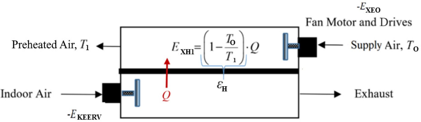
The simple HRV diagram taken from the ASHRAE Handbook shown in Figure 1 must include the electrical exergy required by the oversized/added fan motors to properly circulate the air through the HRV unit to overcome the associated pressure losses. Figure 2 shows this first step of this new model, which is the base case without an HP.
The total CO2 emissions responsibility, ΣCO2 of an HRV unit for a given thermal load (Q), or any other similar system, which consumes electrical energy from the grid is a sum of the direct emissions responsibility if power is delivered from a thermal plant and avoidable CO2 emissions, namely CO2, according to exergy destructions:
(1)
The first term in eq. (1) represents the First Law component of emissions and the second term represents the Second Law component of emissions. The factor cimix is the unit CO2 content of the primary fuel mix used in the energy sector that provides power to drive the fan, pumps, etc., of the on-site systems and equipment, like the fan motors of HRV units. The efficiency (ηT) covers the thermal plant, transmission, and distribution of power in the grid. Eq. (1) at the same time represents the ozone depletion potential and global warming potential because CO2 emissions are the prime cause of both. Besides, if mechanical compression systems with refrigerants like HPs are used, further ozone depletion takes place. The same also holds for the attached cooling towers, while they release excess water vapor to the atmosphere, with the greenhouse effect.
This model recognizes the presence of fans and their motors simply dedicated or attributed to the HRV boundary. It also recognizes the unit exergy of heat and power. According to this model, exergy gain from the exhaust heat transfer (Q) is given in eq. (2). This exergy gain raises the outdoor air temperature from To to T1:
(2)
The exergy gain in the HRV unit must be greater or at least equal to the exergy demand of fan motors on the outdoor and the exhaust side of the HRV unit:
(3)
The subscript 1 denotes HRV. If there is a coupled system like an HP, it is denoted by the subscript 2. Thermal exergy gain in the HRV unit, namely EXH1 is a linear function of the airflow rate (V) where fan power, thus the corresponding fan exergy demand is a power function of V [see eq. (8)]. Therefore, there is a limit on the maximum airflow rate and the corresponding thermal exergy gain. The maximum flow rate allowed in many cases is less than the hourly fresh air requirement for maintaining the indoor air quality. Therefore, the remaining fresh air needs to be heated by another HVAC system, like an HP and the mix must be brought to the final supply air temperature (Tf). This requires the optimization of the outdoor airflow rate split between the HRV unit and another air heating system, like an A-A HP, operated by grid power.
An HRV unit, which is expected to save from total CO2 emissions responsibility, the return of embodied exergy as well as investment, and energy spending must be accordingly analyzed. Table 3 compiles energy, exergy, and CO2 emission embodiments for the major material types typically used in the manufacturing process of HRV units. Typically, steel, aluminum, and copper are used. Embodiments are expected to be recovered during the operation of the HRV. The commercial HRV model 1 as shown in Table 1 weighs 112 kg and has a material mix of about 50 kg aluminum, 45 kg steel, and 17 kg copper. Therefore, the total embodied CO2 for this model is 5,343.4 kg CO2. Other embodiments were also calculated by using Table 3:
Embodied exergy (EXEM): 15,925 MJ (4,423.6 kWh);
Embodied energy (EEM): 11,983 MJ (3,328.6 kWh);
Total embodied CO2 (ΣCO2EM): 5,343.4 kg CO2;
Investment cost (I): USD 1,200 (given, including installation costs).
If the HRV unit is operated for 3,000 hours (moderate climate) in a heating season at an average thermal power of 5 kW, then the seasonal thermal energy savings will be 15,000 kWh. However, if the HRV fans require grid power, then the corresponding energy demand must be subtracted. With a seasonal average, COP of 14.03, electrical energy spending is 1,069 kWh (15,000 kWh/14.03). It must be noted that the unit exergy of heat and the unit exergy of electricity is quite different and they should not be simply added or subtracted. However, just to demonstrate how the calculations are carried out in the industry, here they are subtracted. Therefore, this operation gives a net energy saving (Es) of 13,931 kWh (according to the First Law only).
Typical Embodied energy, exergy and CO2 emissions of materials used [32], [33]
| Material | Embodied | ΣCO2EM 3 + 5 [kg/kg] | |||
|---|---|---|---|---|---|
| Energy (E) [MJ/kg] | CO2E [kg/kg] | Exergy (EX) [MJ/kg] | CO2X kg/kg] | ||
| 1 | 2 | 3 | 4 | 5 | 6 |
| Aluminum | 170 | 31.5 | 249 | 53.6 | 85.1 |
| Refined copper | 99 | 9.7 | 80 | 8 | 17.7 |
| Steel | 40 | 7.4 | 47 | 10.1 | 17.5 |
Embodied exergy payback (YX). Because COPEX is always less than 1 there is no finite payback period for embodied exergy. There is always net exergy destruction (from Table 1, COPEX is 0.613).
More clearly speaking, the exergy deficit is the difference between the exergy of thermal energy saved (24,000 kWh) and the exergy of the electrical energy used (1,710.6): Exergy gain = 15,000 × (1 - 273 K/290.8 K) – 1,069 (1) = -150.8 kWh/heating season. The negative sign indicates exergy destruction. The unit exergy of electricity is 1 kW/kW.
Embodied energy payback (YE):
(4)
Embodied CO2 payback :
(5)
In eq. (5), the term 0.2 kg CO2/kWh is the unit CO2 content, ci of natural-gas based on 1 kWh of the lower heating value, used in a boiler with a seasonal-average First Law efficiency of 0.85, which is assumed to be replaced by the HRV unit with a COP value (14.03 from Table 1). The second term is the indirect CO2 responsibility of the HRV unit, based on the use of grid power supplied from a natural-gas thermal plant. 0.30 is the power generation and transmission efficiency of the grid on average. The last term in eq. (5) represents the avoidable CO2 emissions responsibility, CO2 of the HRV unit [see eq. (25)]. Because the COPEX value is less than 1 (0.613 from Table 1), the last negative term makes the denominator close to or less than zero, implying that the net CO2 emissions savings are almost none. Therefore, the CO2 embodiment is not practically recovered.
Embodied investment payback (Yc). The simple investment payback Yc is the function of investment cost (I), cost of fuel (Cf), boiler efficiency (ηB), COP of HRV, cost of electricity (CE), and the seasonal energy savings (Es):
(6)
If the average natural gas price Cf is about 0.035 USD/kWh and ηB is 0.85, the average electricity price CE is 0.1 USD/kWh, COP in heating is 14.03 (Table 1, column 1), then from eq. (6), the investment payback period Yc will be about 2.5 heating seasons.
New definitions about returns given above show that although HRV systems with fast economic returns are recommended for IAQ applications due to their First Law efficiency [1], they do not favorably payback in terms of exergy and CO2 embodiments while more exergy is destroyed than recovered from the waste heat unless the electrical power is supplied by on-site or near-site renewables. This disadvantage becomes more critical if the net negative added value to the environment in terms of ODP and GWP, which the HRV unit and the HP are directly and indirectly responsible are also considered with their interactions [see Figure 3 and eq. (27)]. In addition to the base case mentioned above, three case studies presented herein investigate whether the exergy rationality and environmental impact may be improved, namely by adding an HP in a parallel position or a series position (downstream) of the HRV unit, respectively, and a stand-alone HP:
Case 1: HRV coupled with an HP in parallel;
Case 2: HRV coupled with an HP in series;
Case 3: HP only.
To optimize the split of the total flow rate of the outdoor air intake between the HRV and the HP units for maximum exergy-based performance, a new model was developed, which is shown in Figure 3.
Isolated model for the operational diagram of the method with a parallel HP (note: Main HVAC fans that are served by the HPs are excluded)
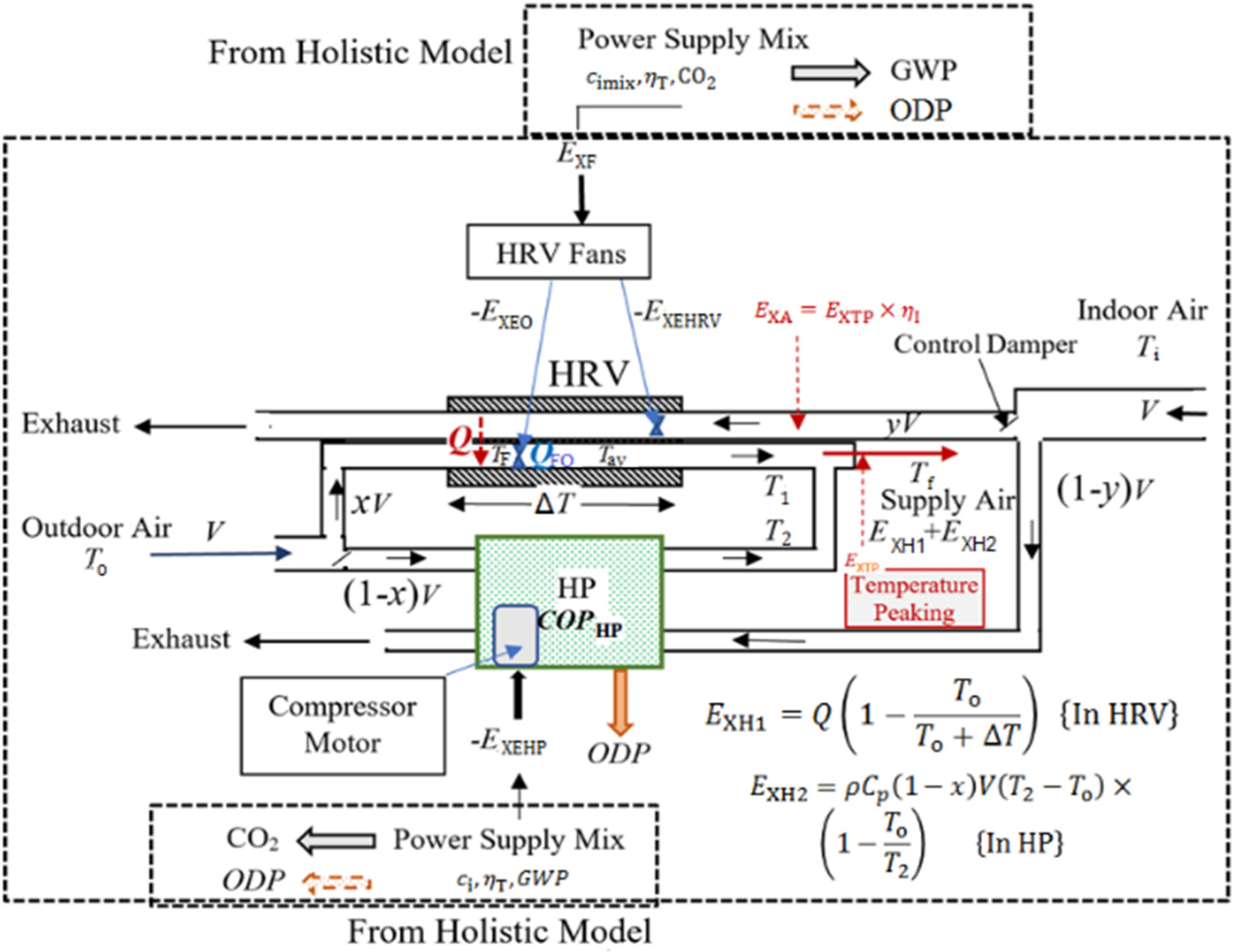
This method identifies two parallel air flow ducts. One of them delivers outdoor air to the HRV unit. The second duct delivers the remaining outdoor airflow to the HP. Hereby, the outdoor air split ratio is represented by ratio x. If x is zero, it means that HRV is not functioning (or absent). If x is 1, then it means that the HP is not functioning (or absent). Airflow rates in the HRV unit are limited such that thermal exergy gain obtained (EXH1) by heating the incoming outdoor air to a temperature of T1 must be higher than the electrical exergy demand of the two fans motors and the fan drive. This system designed and operating under optimum conditions is expected to also improve the ratio of energy consumption of the building to the energy consumption of the ventilation system, which may be similarly defined in terms of the PUE factor for data centers [5].
Across the HRV unit, there are two counter-air flows, namely the exhaust air at a flow rate of yV and the fresh outdoor airflow rate of xV. Assuming that fans at both sides of the HRV unit are identical, then:
(7)
Here, f in the last term represents the fan characteristic, ηF and ηbm are the fan and motor-belt efficiencies, respectively. They are assumed to be approximately constant concerning their flow rates during operation. EXEHRV and EXO represent the exergy demand of both fans, which operate on electricity. For standard air conditions at sea level and 15 °C, it may be taken that ρ is 1.225 kg/m3 and Cp is (1.026 kJ/kg·K). Then, along with the following relationship between ΔP and V for rectangular ducts:
(8)
(9)
The power (m) is 1.82 for the galvanized ducts. For other inner linings, sizes, and geometry, m changes between 1.8 to 1.9 [30]. According to eq. (7), the maximum flow rate between To and T1 (ΔT) in the HRV unit is limited:
(10)
(11)
(12)
then solving for T1{T1 > To}:
(13)
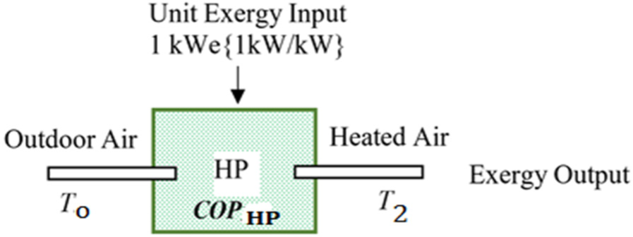
The term x is subjected to the optimization algorithm [see eq. (17) and eq. (19a)]. The ratio y is separately controlled by optimized operating conditions of the HP for a given x ratio. T1 is a function of x for a required supply air temperature Tf. To solve T1, T2 is solved first for optimum exergy output in terms of the exergy-based COPHP, namely COPEXHP written only for the HP itself according to the ideal Carnot cycle as represented in Figure 4:
(14)
The COPHP term may be linearly expressed in a given, narrow operating range:
(15)
When the partial derivative of the simultaneous solution of eq. (14) and eq. (15) with respect to T2 is equated to zero the optimum value of T2 for maximum COPEXHP is obtained. In eq. (15), q and r factors are the linearization coefficients for the COPHP. If q is equal to 6 and r is 0.05 K-1 for a given HP operating in a temperature range between 273 K and 300 K at an outdoor temperature, To of 283 K then the optimum T2 is 337.7 K:
(16)
Exergy input and output in an A-A HP
If the required supply air temperature Tf is 310 K and x is 0.75, then, from eq. (13) T1 is 300.8 K. Therefore, the optimum temperature T2 for the HP is out of range. To avoid this condition, a different type or model of the HP with different q and r values may be selected. This solution, however, is subject to the maximum allowable airflow rate (V) that is limited by eq. (10). Now, knowing the optimum T2 and knowing T1 in terms of T2, for a known total fresh air flow rate requirement V, an optimization function (OF) may be written in terms of x for maximum exergy gain from the exhaust air. If the electric motor of the additional/oversized fan is inside the HRV duct, the last term in eq. (17) represents the heat gain from the electric motor and its drive casing. This term adds exergy in winter (heating) but reduces exergy from the OF term in summer (cooling). If the electric motor and the casing are placed outside the ducts, this term drops:
(17)
The approximation in eq. (18), which was derived from the information available in [31], [33], calculates QFO. In this equation, H is a number less than one, which represents the net conversion ratio of the electrical power input, which is not converted to the shaft power to the heat transferred to the airflow in HRV:
(18)
To bring the supply temperature to the required design temperature Tf at the exit of terminal units for proper satisfaction of the sensible indoor space heating load, the temperature may require to be peaked by an auxiliary heating system, which is arranged in tandem to the HRV unit with or without the HP (see Figure 3). This auxiliary system might use fossil fuel or power, and therefore additional ODP and GDP take place. EXTP denotes the additional exergy spending for temperature peaking. In the quasi-closed outdoor/indoor system of the HRV unit, the exhaust air bears part of this thermal exergy and transfers it back to the outdoor fresh air drawn in with a thermal efficiency ηI across the HE of HRV or HP. Because this thermal exergy is finite, as opposed to ambient (practically infinite) sources like air or water, and fossil fuel or power input takes place during temperature peaking upstream in the indoor ducts, it may not be treated as ambient energy like the ground heat, ambient air, seawater, etc. Therefore, it must appear in the definition of COPEX, while traditional COP calculations often ignore this term (ambient sources). Referring to eq. (17), the overall COPEX of the system modeled in Figure 3, namely the HRV+ parallel HP Case 1, is given in eq. (19a). The objective is to maximize COPEXHRV+HP:
(19a)
In eq. (19a), EXTP is the sum of the partial contributions of EXH1 and EXH2:
(19b)
and:
(20)
All terms in the objective function OF and the COPEXHRV+HP function given in eq. (17) and eq. (19a), respectively, contain the split factor x, in such a manner that the objective function is a single function of this variable x with all other given and independently solved variables like To and T2, respectively. Therefore, this model also provides an exergy-based control algorithm to maintain the maximum exergy rationality during operating under dynamic outdoor and indoor conditions. For the x < 1 condition, y is (1 - x). For x = 1 condition, y is either equal to 0 (Case 1) or equal to x, which is also equal to 1 when the HP is in series with the HRV unit (Case 2).
In this case, HP is placed downstream of the HRV unit in series such that the total airflow passes through both the HRV and the HP units. Therefore, x and y are equal to each other, and mathematically speaking, both are equal to one. The downstream position is a better position for the HP, compared to an upstream position where colder air supply will reduce the COP of the HP. The same eq. (19a) applies with x = y = 1 to determine the maximum COPEX value for a given design or operating conditions. Furthermore, in eq. (17) and eq. (19a), Tf replaces T2. T1, which is determined from the HRV specifications, replaces To in eq. (16). Consequently, eq. (12) and eq. (13) are not used.
The same eq. (17) applies with x = 0, y = 1, which means that there is not any HRV unit and the HP is exposed directly to the outdoor air at temperature To and has to deliver heat at the final supply temperature Tf because another auxiliary temperature-peaking system is not desirable from the cost and exergy points of view. This means that the HP has to operate at a lower COPHP, while a larger T, which is equal to (Tf - To) exists. In Case 3, T2 directly replaces Tf at the absence of an auxiliary temperature-peaking heating system. See also eq. (14) and eq. (15) for temperature replacements.
In the same model, the additional (avoidable) CO2 emissions responsibility, namely ΔCO2 due to exergy destructions is explained by the REMM [34]. Figure 5 shows a sample exergy flow bar according to REMM for a single HRV unit that is driven by grid power.
Exergy flow bar for HRV unit in space heating mode (not to scale)
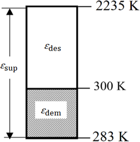
This is a simple exergy flow bar, which covers only one application, one system, and one energy source. This bar is drawn starting from top showing the primary energy source temperature Tf to the final application temperature in the HRV unit (indoor supply temperature at 300 K) and then to the environment reference temperature (Tref) (283 K) at the bottom. It is assumed that electric power is supplied through the grid where the electric power is generated in a natural-gas power plant. 2,235 K is the adiabatic flame temperature of the natural gas. In this sample case, the exergy utilized (for the space heating demand), dem starting from an outdoor temperature To of 283 K, and ending at the outdoors is given by eq. (21), according to the ideal Carnot cycle:
(21)
while the original exergy supplied (sup) at the power plant is given by eq. (22):
(22)
According to REMM, if the major exergy destruction takes place at the upstream of the useful application (heat recovery), like in Figure 5, then ψR, which is the Rational Exergy Management Efficiency is the ratio of dem and sup [34]. According to this definition, ψR is 0.064 for the above numerical example:
(23)
For 1 kW of exergy power supply:
(24)
Here, des is equated to 1 - COPEX. Referring to eq. (23) and the identity in eq. (24), ψR seems to be equal to COPEX. However, because ψR is a measure of exergy rationality in terms of ideal Carnot cycle while COPEX is a measure of exergy efficiency in terms of various exergy destructions taking place in the system, this identity may not hold for other more complex systems, while COPEX definition approaches to the Second Law efficiency. If part of the exergy input to preheating is from the reclaimed heat that is a result of temperature peaking EXTP, appears in the denominator of the COPEX term given in eq. (19a). Therefore, for non-ambient exergy inputs, COPEX in eq. (24) must be corrected by a factor w. This factor is about 0.85 in building applications of HRV and HPs. If there is no temperature peaking, then w is 1. This rule also applies to eq. (25) given below.
For a given unit exergy destruction εdes taking place in any energy conversion system or equipment like an HRV, its natural-gas equivalence that is necessary to spend to replace the said destroyed exergy will be (εdes/0.87). Assuming that this exergy destruction is replaced in an equal amount of exergy generation in a non-condensing natural-gas boiler with an average reference thermal efficiency of 0.85, one may find the associated avoidable CO2 emissions responsibility. In eq. (25), 0.2 is the unit CO2 emission of natural gas per 1 kWh of its lower heating value ci. Then, eq. (25) simply relates the avoidable CO2 emissions to the destroyed unit exergy per kWh of heat. For the heat pump-alone case (Case 3), Figure 5 applies where εdem is replaced by εdem × COP. If COP is 5 then ψR is 5 × 0.064, which is 0.32:
(25)
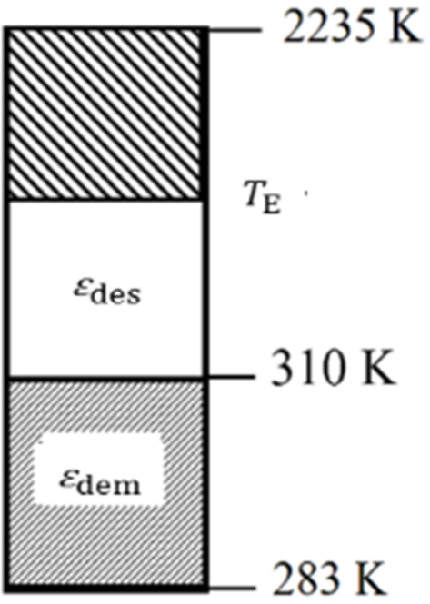
In this case, CO2 from eq. (25) is 0.18 kg CO2/kWh of unit heat, Q = 1 kWh, supplied assuming that no temperature peaking takes place (w = 1). Depending on the x value for an HRV and HP combination, the average ψR may be calculated by an algebraic weighted sum. If a fuel cell or micro-cogeneration unit replaces HRV and the HP, the exergy flow bar looks similar to the one given in Figure 6, because both systems generate electricity on the site from the natural gas fuel input. Fuel cell, however, has a lower heat output temperature TE. In this case, ψR has a different definition [34]. If for example, TE is 500 K for the micro-cogeneration unit and 350 K for a fuel cell, then ΨR values are 0.56 and 0.87, respectively:
(26)
Exergy flow diagram for fuel cell and micro-cogeneration units
Until now, ODP and GWP have been separately treated regarding the impact of systems in the built environment, by ignoring the important relationship between the two. Therefore, a so-called zero-ODP refrigerant used in the compressor of an HP (for example, R227ea), which has a very high GWP value ‒ about 2,300 is recommended for reducing the ozone depletion effect in the atmosphere. Any increase in GWP increases ODP. While the air temperature in the lower atmosphere increases with an increase in greenhouse gases, air temperature in the stratosphere cools due to the blanketing effect of the greenhouse gases. This cooling triggers more ozone depletion. Therefore, GWP has a definite relationship with ODP. Conversely, any expansion in the ozone hole increases global warming. Although verified by observations this relationship was not mathematically expressed practically. To simply show the combined effect of a system like an HP with refrigerant leakages, a new expression, namely ODI was developed:
(27)
This equation combines ODP and GWP of a given refrigerant by also referring to the atmospheric residence time ALT. The power (t) regarding the GWP term in eq. (27) includes the combined effect of water vapor released to the atmosphere due to fossil fuel combustion, from attached cooling towers or increased evaporation from warming seas, lakes, or rivers, which accept the reject heat from thermal power plants that provide electricity to air conditioners and HPs. Collection of condensates from condensing boilers do not help, because additional exergy destructions taking place during condensing the flue gas overweighs them in terms of avoidable CO2 emissions responsibility of condensing boilers. Accordingly, there is neither any refrigerant nor heating and cooling equipment with compression or absorption cycle with actually non-zero ODI even if their reported ODP values are 0. For example, compare R744 and R227ea:
(a)
(b)
For s = 0. 1, t = 0.03 (including water vapor effect), and u = 0.01 values in hand, their ODI values are:
(a)
(b)
These calculations ignore the additional effect of cooling towers, while they release moisture to the atmosphere with additional ODI. Therefore, cooling towers need to be eliminated or minimized by utilizing the reject heat. Dry cooling towers on the other hand use more electrical energy and they are again responsible for additional ODI, depending upon where the electricity comes from and how it is generated.
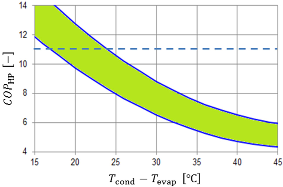
It has been shown that the new method can be easily applied to the entire spectrum of any combination of HRV and HP units simply by varying the x and y values. Hence, it is a versatile tool both for design, retrofit, and control of HRV units with or without HPs or any other auxiliary heating (cooling) units coupled to them, particularly in green buildings, where both the unit exergy demand of HVAC functions and unit exergy supply of renewable or waste energy resources are small. The need for such a sensitive balance in such a small exergy range requires an accurate, exergy-based optimum solution algorithm. A sample warehouse case with HRV and parallel HP combinations for a unit airflow rate of V = 1 m3/s has been analyzed. Standard air conditions apply. The temperature of the supply air is not peaked. Table 4 provides the constant terms used. Eq. (17) and eq. (19a) were used for a simple search of the optimum x and thus y values for the maximum OF value in an MS Excel worksheet to determine the optimum x and thus y values for maximum OF. The results are shown in Figure 7. It is interesting to note that contrary to the general belief, HPs even with a COP value of 6 in heating mode does not contribute to sustainability and do not offer an optimum combination. OF values are always lower than the HRV-only case (x = 1), when the Second Law comes into the picture: Figure 7 clearly shows that unless the COP is equal or more than 11 for this sample case, the HRV-only option (x = 1) is always better. Even if such high COP values are possible at industrial scale or in nZEXB applications, such that the maximum OF (5.8 kW) in this case study takes place at the condition of x = 0.45, COPEX is less than 1 as is true for all other options given in Table 5. Any mechanical system running on grid power is not exergy rational.
Constant terms for the case study [in eq. (17) and eq. (19a)]
| Constant | a | c | d | H | ηF ηbm | m | q | r | To | To | To | EXTP [kW] |
|---|---|---|---|---|---|---|---|---|---|---|---|---|
| [K] | ||||||||||||
| Value | 0.2 | 0.1 | 0.8 | 0.9 | 0.75 | 1.8 | 6 | 0.05 | 273 | 310 | 345 | 0 |
Change of OF value with x and y combinations for the base case and the three cases of HRV and HP combinations
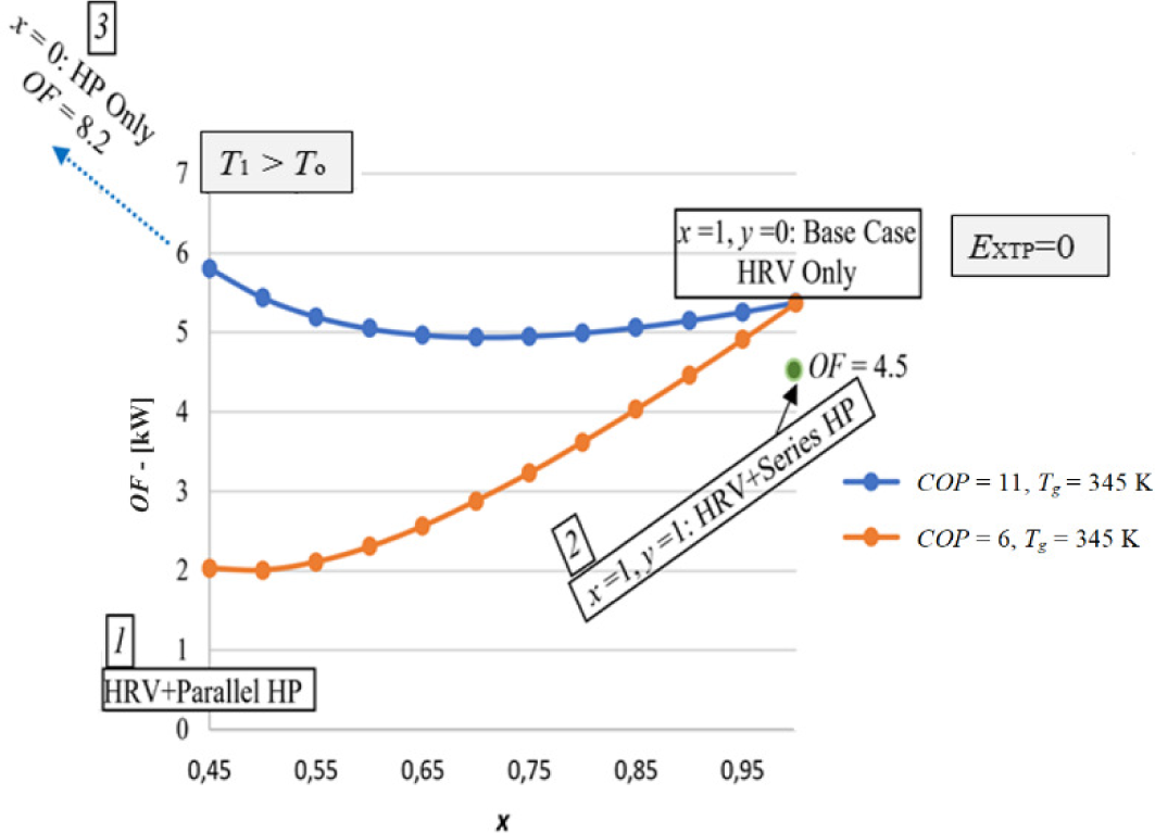
In Figure 7, x starts from 0.45, because T1 > To condition must be satisfied. If the curve is extended towards the x = 0 point of the graph, then the HP-only condition is reached. In this case OF is the highest, which is 8.2, provided that COPHP > 11 condition applies. If the HP is coupled in series, downstream with HRV, OF is at a single point on OF versus x diagram, because x and y are both set to 1. Here the OF term is 4.5.
Comparison with a condensing boiler, micro-cogeneration, and fuel cell
| System cases and other options | ODI (F gas) | /ODI | CO2 | ΔCO2 | ∑CO2 | ΔCO2/CO2 | COP | COPEX | |
|---|---|---|---|---|---|---|---|---|---|
| [kg CO2/kWh] | |||||||||
| Base case: HRV only | 0.102 | 0.061 | 2.25 | 0.047 | 0.103 | 0.15 | 2.2 | 14.03 | 0.61 |
| Case 1: HRV + Parallel HP | 0.405 | 0.1122 | 3.6 | 0.07 | 0.037 | 0.10 | 0.74 | 9.063 | 0.86 |
| Case 2: HRV + Series HP | 0.54 | 0.08 | 6.75 | 0.05 | 0.013 | 0.063 | 0.26 | 12.2 | 0.95 |
| Case 3: HP only | 0.514 | 0.1784 | 3.79 | 0.06 | 0.088 | 0.148 | 1.47 | 11 | 0.67 |
| Boiler only | 0.135 | 0.275 | 0.5 | 0.25 | 0.254 | 0.504 | 1 | 0.8 | 0.05 |
| Micro-Cogeneration | 0.87 | 0.136 | 6.7 | 0.22 | 0.120 | 0.25 | 0.54 | 0.9 | 0.55 |
| Fuell cell | 0.57 | 0.15 | 3.8 | 0.22 | 0.11 | 0.32 | 0.50 | 0.9 | 0.6 |
| Electric resistance7 | 0.06 | 0.2 | 0.3 | 0.67 | 0.251 | 0.921 | 0.37 | 1 | 0.06 |
With ηT = 0.27 and COP of HRV = 14
Equal split of air preheating (in Figure 1)
With x = 0.45
With COP = 5
With ηB = 0.85
Power output is prorated
On grid power with ηT: 0.30 and energy supply mix with 0.4 kg CO2/kWh for power generation, To = 273 K for space heating
Note: CO2 = 0.27(1 – wּּּ × COPEX) {0.85 ≤ w ≤ 1}
In this study, the base case (HRV-only case), HRV with HP (parallel and series), HP-only, boiler, micro-cogeneration, fuel cell, and electric resistance heating with grid power were compared according to their direct CO2 emissions and the avoidable CO2 emissions, namely CO2, and ODI responsibilities. The results are given in Table 5.
The values listed in Table 5 for various systems and equipment remarkably show that avoidable CO2 emissions, which are directly related to exergy destructions are as large as direct CO2 emissions of equipment and systems. This might be a clue for the latest findings that sea levels will rise twice as much as previously anticipated.
Because exergy is not measured but calculated, the rather hidden to many CO2 emissions are avoidable by improving COPEX values and this puts exergy analysis into an important game maker role for avoiding global warming challenge, which is becoming a state of emergency lately. It may be argued that the major reason for low COPEX values in the reclamation of waste heat originates from the use of electric fans, pumps, and other ancillaries and they may be avoided by the use of heat pipes.
This argument may seem to be valid at a first glance but certain heat pipes, especially containing refrigerants, like R-134a [35] are claimed to have zero ODP, but in fact, they have non-zero ODI [see eq. (27)]. Therefore, while CO2 emissions from power plants are avoided by reducing the use of grid power in heat recovery systems and equipment, ODI increases, which interrelates GWP to ODP. Therefore, the result is almost the same in terms of global warming. The use of water-ethanol, acetone, methanol mixtures with very low ODI may be other options but they have high smog-formation potential. Then the remaining solution for a sustained avoidance of large amounts of exergy destructions is new exchanger designs, extending even to morphing HRV units with 4D printing technology, with embedded flexibility along with higher fan (including morphing fan blades) and higher motor efficiencies, supplied with renewable electricity on site.
The above discussion may hold from the tiniest HRV unit in a small home to waste heat recovery from thermal power plants like heat recovery from stacks of coal-fired power plants. In such cases, again, the exergy recovered from the waste heat in the stack may be less than the exergy spent for the heat recovery mechanisms like pumps and additional stack fans if a careful design and exergy-based optimum control is not implemented. The boiler-only option has the lowest COPEX value. The highest COPEX value, which is 0.95, belongs to HRV + Series HP case, provided that COPHP is 11. Otherwise, i.e., for the condition of COPHP < 11, there is no optimum solution and the singular solution goes to the x = 1 point (HRV only). The next better case is the parallel HP case and then the base case with COPEX = 0.613. The lowest COPEX is for electric resistance heating case that is running on grid electricity. This case has also the highest total CO2 emissions rate.
The new composite index, namely ψR/ODI, which rates a system according to its exergy rationality per environmental footprint in terms of ODI is highest for HRV + Series HP case (Case 2). Therefore, it seems that the series coupling of the HP is a better alternative compared to parallel coupling with HRV. In turn, the HRV option has the lowest ODI value indexed to F gas. ODI originates from the GWP of the fossil fuels used in generating the electric power necessary for driving the oversized/added portion of the ventilating fans of the HRV unit.
A COPHP value greater or equal to 11 is only possible for industrial HPs, using ammonia refrigerant. Figure 8 shows different cases of evaporator and condenser temperature cases. Obviously, in industrial scale, COPHP > 11 may be achieved at a small condenser and evaporator temperature differences (see Figure 9). According to Figure 9, the difference must be less than 20 K. This provides the condition that first the outdoor climate must be moderate and the building must be nZEXB type, which demands lower heating temperature, second, due to the industrial size of such HPs, district energy systems must replace individual heating and cooling systems. It is hard to achieve such high COP values in smaller application sizes, like residential and small office buildings, unless the condenser/evaporator temperature differences are very small.
Change of COPHP with condenser and evaporator temperatures in industrial scale [37]
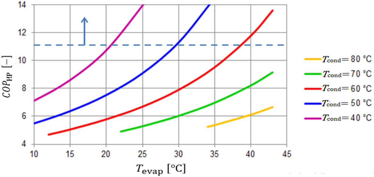
Change of COPHP with the condenser and the evaporator temperature difference [37]
This requirement for satisfying the condition COPHP > 11 may be derived by referring to eq. (15) by writing the temperature difference between the outdoor and supply temperatures. This derivation imposes a lower limit on the outdoor air temperature:
(28)
A simultaneous solution of eq. (27) and eq. (28) may further relate EXP to To. Thus, a variable-speed fan motor, which follows the outdoor temperature is essential. Eq. (28) further indicates that a residential HP with high q value and the low r-value is desirable. At the same time, to operate the HP at lower outdoor temperatures in colder climates, lower Tf must be applied. This is only possible by decoupling the sensible heating (or cooling) loads and ventilation loads and dedicating sensible loads to radiant panel systems [36]. For example, if Tf for ventilation only case is 295 K (22 °C) in an nZEXB, q is 12, and r is 0.05 K-1, then from eq. (28), the outdoor temperature must be higher than 275 K (2 °C). This is a serious restriction for the operation of the HP in HRV coupled applications, particularly during cold climates.
On the other hand, the electrical power exergy demand EXF for an HRV unit for a given sensible load Q is limited and must be related to the To limit given in eq. (28):
(29)
Table 5 shows that for all known electro-mechanical systems used for heat recovery in buildings, which seem to be very profitable and environment-friendly, COPEX values, which reveal and evaluate their global sustainability aspects better than COP are less than 1, which indicate that all electromechanical systems naturally destroy exergy and the best alternative is to minimize exergy destructions by an exergy-based method, like the one presented in this paper.
However, Table 5 deals only with HRV-dedicated systems and equipment covered by the isolated model shown in Figure 3. The origin of the electrical power supply is not included. If a holistic insight about the performance and responsibilities of HRV units and their ancillaries in the built environment is required, an expanded model is possible if the domain is stretched upstream back to the origin of the electrical power generation, transmission, and transformation simply by introducing their total efficiency ηT to eq. (17), which is shown in eq. (30). This expansion affects the isolated model in Figure 3 at the HRV and HP power inputs. This simple introduction makes it possible to trace the responsibilities of HRV units back to the primary fuel input concerning the electrical power supply through the grid (Figure 10). Terminal units in this model are represented by the last term regarding QFO in eq. (17) and eq. (30):
(30)
The current average ηT value in EU28- countries is 0.4 [37]. Therefore, the HRV fan term (the third term) in eq. (17) increases by a factor of 2.5 (1/0.4). The OF values plotted in Figure 7 will decrease but the overall conclusions will remain unchanged. While eq. (1) already includes the term ηT, the holistic model may be applied to modify the CO2 emission responsibility term, because there are additional exergy destructions taking place at the thermal power plants.
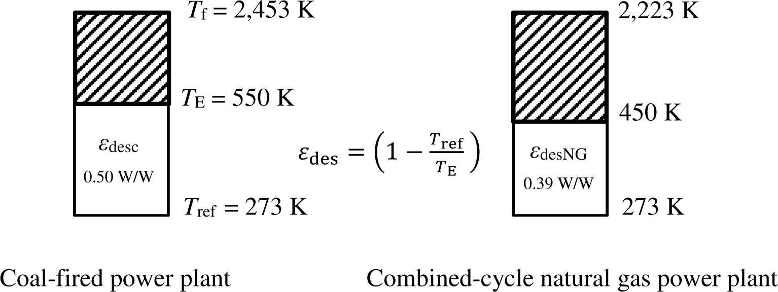
Two types of plants were identified namely a coal-fired (anthracite) plant with economizers and a combined-cycle, natural gas plant. Respective adiabatic flame (exergy source) temperatures are 2,453 K and 2,343 K. Reference temperature is 273 K. Exit temperature from the power generation stage is 550 K for a coal-fired plant and 450 K for the combined cycle, natural gas plant.
Expanded (holistic) model of heat recovery in a building with grid power
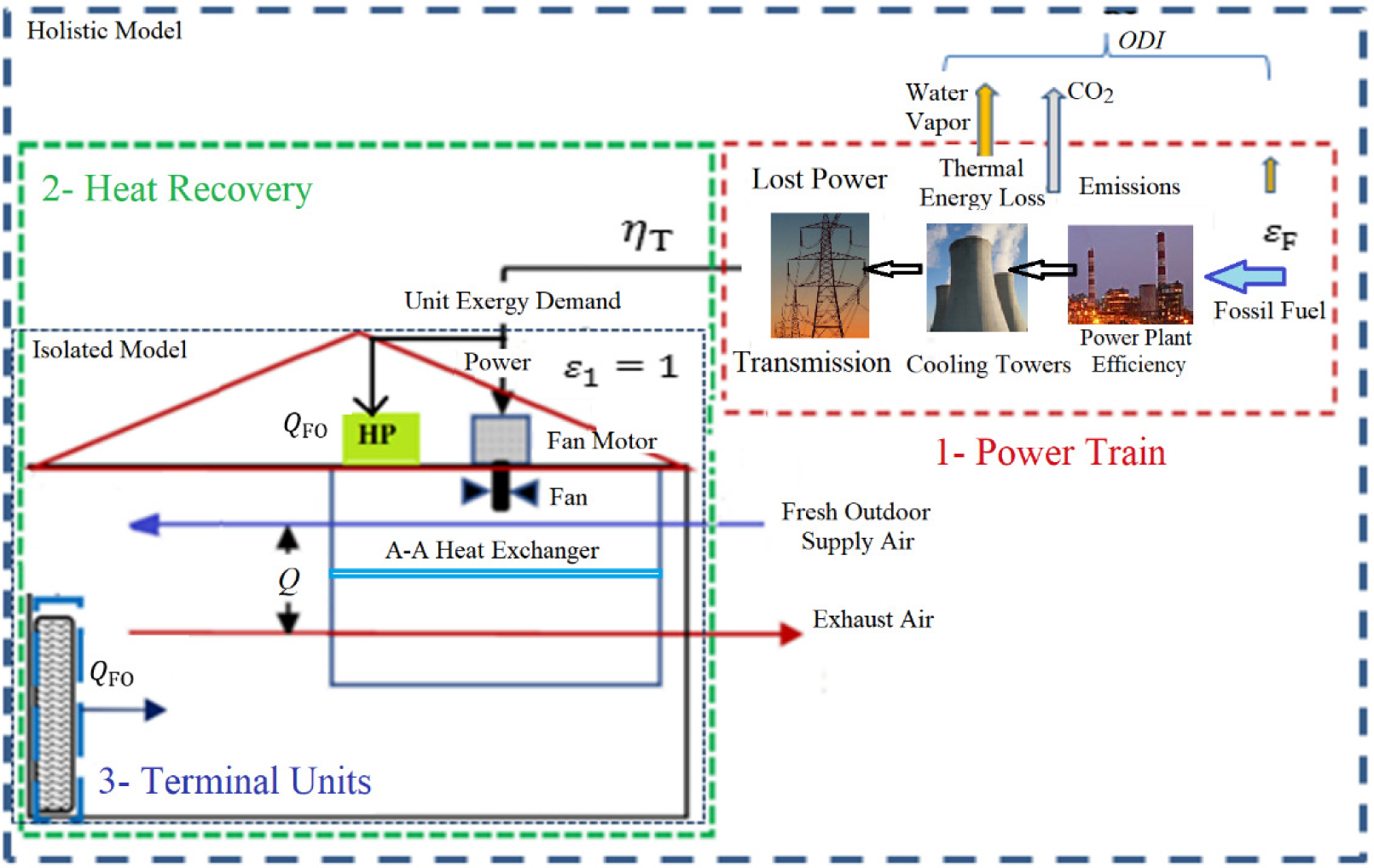
Figure 11 shows the destroyed unit exergy of these two types of power plants. Let cic and ciNG are the capacity-weighted factors of unit CO2 emissions of installed thermal power plants, namely coal-fired and natural-gas-fired, respectively. Then for the energy mix of a given country, represented by cimix that may be approximated from eq. (32), the second term of eq. (1) is modified in the following form:
(31)
(32)
Here, 0.6 and 0.2 are the unit CO2 emission rates of anthracite coal and natural gas, respectively, at adiabatic conditions in the air. The unit is kg CO2/kWh of fuel LHV.
Exergy destructions in two types of thermal power plants
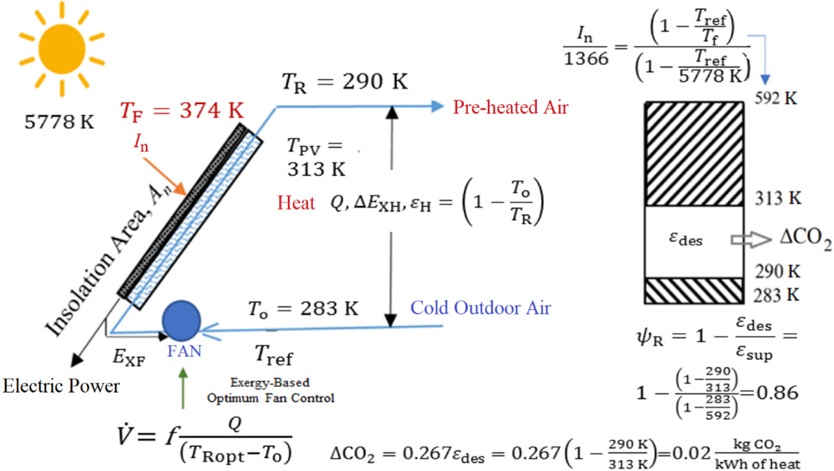
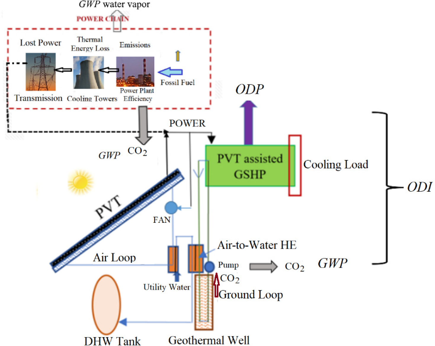
A better approach to eliminate the power supply-related disadvantages that have been revealed by the holistic model for the built environment is to move on towards passive houses. A renewable energy system example is the passive preheating of the outdoor air with a solar air heater system, typically installed on the roof of the sustainable building, which operates with the natural convection of colder outdoor air passing through the sandwiched duct beneath the PV panel. While colder air enters the PVT from the bottom, it rises and the indoor ventilation air is preheated. According to Figure 12, solar radiation intensity normal to the PVT surface In is 750 W/m2. The Carnot cycle-equivalent solar source temperature Tsol, corresponding to In is calculated from eq. (33) [34]. 1,366 W/m2 is the average value of the solar constant. Even when the A-A PVT operates without a fan (natural convection) it is responsible for avoidable CO2 emissions:
(33)
A-A (PVT) panel with natural circulation: winter mode
In the summer period, additional equipment and exergy sinks are involved, which are shown in Figure 13. The PVT panel is cooled by air, which in turn, is cooled by the utility water. Utility water after being warmed by exchanging heat with the exit air from the PVT panel is further heated through a ground-source HP on demand and at the absence of the cooling load, to avoid the Legionella disease risk and then stored in a DHW tank. Part of the electric power generated by the PV cells drives the GSHP, which satisfies the space cooling loads during the day time. The reject heat goes to the ground well. The air loop normally depends again on natural convection while a water pump is introduced for the ground loop. However, water pumps require less power than fans in transferring the same amount of heat [31]. In this arrangement, there is direct emissions responsibility at the power plant feeding the pumps through the grid.
Regarding a PVT system, the total output is not a simple addition of electricity and heat, because of their different unit exergy. Heat and cold also have different unit exergy. Depending on the ratio of power and heat generation, the rational exergy management efficiency ψR varies, which directly affects the added value of a PVT. Therefore, the cost of a PVT must be levelized according to exergy in terms of ψR. In this study, ELC has been developed, which combines exergy rationality in terms of ψR, the selling price PC, embodied costs EM, panel area A, and panel weight W [38]. ELC serves for establishing a new comparative metric, which may also be used for rating the exergo-economic performance of a PVT system:
(34)
Furthermore, a second new metric, TI evaluates any system in terms of its energy efficiency (First Law), energy rationality (Second Law), and ODI. This gives a total evaluation index:
(35)
A-A (PVT) panel with natural circulation: summer mode
According to a recent study and an embodied exergy model about horizontal development vs. vertical development in new settlements in the built environment by Kılkış and Kılkış [39], exergy is a game-changer. This also applies to the energy recovery in ventilation as shown in this paper. An HRV unit may seem very beneficial in economic and energy savings potential and even maybe touted to be environmentally benign. The same HRV unit proves to be exergy- irrational with existing technology, which depends upon grid electricity. First of all, more efficient electric motors, fans, and HE with less pressure drop across them need to be designed and new alloys and composites have to be used with fewer embodiments during their manufacture. However, these have diminishing returns in terms of the First Law.
Renewable energy sources with little or no electric power requirement must be utilized for effective solutions to make the COPEX value approach or even exceed 1. Even if on-site solar electricity is used like the one shown in Figure 14, the Second Law asks the next question about what is the best rational way of using this electricity, either in an HRV unit or in public transport, and questions keep going on until the best allocation scheme of renewable energy sources is set in a given district and set of buildings. Therefore, it is time to shift to the Second Law if global warming is to be reduced and CO2 emissions are decoupled from the human-focused economic growth. In the meantime, the existing HRC units may be optimized such that COPEX approaches one.
The new model may be transformed into user-friendly software to assist responsible designers and implement exergy-based control algorithms. Such a move will not just mimic existing tools, which are based on the First Law only [8] but far exceed them in optimization with true environmental contributions.
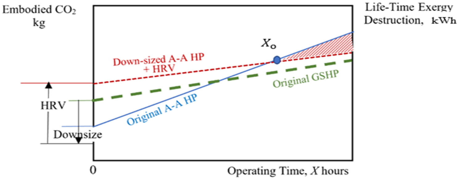
Apart from the above discussions, one needs to realize that the introduction of HRV technology reduces the size of the original HVAC system, like using ground-source or A-A chillers (HPs). The implication is the reduction of the installation cost of the original HVAC system vs. the addition of the HRV unit in series or parallel. The same holds for embodied CO2 emissions related to the material used for the HP and the HRV unit. An original A-A HP is downsized (Figure 14) but a new unit is introduced (HRV). The net embodied CO2 at the beginning (operating time equal to zero) may be higher than the original. This initial increase, however, may be compensated at a time of Xo, because the COP of the HRV unit is higher (thus the slope of the line is smaller) than the HP itself (see Table 5). For a ground-source application, the slope is smaller than the A-A case, because the COP is relatively higher. Yet the initial CO2 embodiment requires additional groundwork and heat exchanging tube material, etc. Therefore, the line is above the A-A case with a smaller slope. This, in general, renders a bigger positive impact of HRV with a bigger HRV, which brings the starting point O is almost to the same point. But because the slope is not high enough this option may not return the CO2 embodiment. All these considerations show how the problem is complicated even if a ‘simple’ HRV application is the question.
Embodied CO2 considerations about downsizing the HVAC equipment vs. introducing HRV
The importance of exergy in waste heat recovery is becoming an important also in the recent literature because the unit exergy of waste heat is comparably less than the unit exergy of electric power used for the heat exchanging process. Some authors have started to consider exergy in their recent literature yet limited to basic thermodynamics and economy. For example, Ayachi et al. [40] determined the choice of system design and working fluids for an organic rankine cycle through a break down thermodynamic (Second-Law) analysis limited to system components. They have investigated two thermal sources, namely dry gas at 165 °C and moist gas at 150 °C. Their objective was to identify recovery solutions suitable for minimizing exergy destruction. In this respect, they analyzed several options including organic rankine and CO2 trans-critical cycles. They concluded that referring to both laws of thermodynamics, the optimum solution may be obtained through a set of suitable design steps, choosing a proper fluid and determining suitable operational such that pinch points are eliminated. Xu et al. [41] in their proposed hybrid Ventilation Air Methane (VAM)-hybrid power generation system and a circulating fluidized bed, claimed that exergy and electricity (power) of the fuel (coal and VAM) are nearly equal to their embodied energies, and thus, the exergy efficiency of the system can be taken nearly equal to its energy efficiency. This claim shows that many authors take side steps to neglect the Second Law. Such research must be expanded to exergy rationality and must include embodied exergy and CO2 emissions. In their study, Erguvan and MacPhee [42] carried out energy and exergy analyses for unsteady cross-flow overheated cylinders. They found that energy efficiency varies between 72% and 98%. The exergy efficiency for corresponding cases ranged between 40% and 64%. Their results suggest that exergy efficiency can be maximized especially in low-temperature applications like ERV systems by choosing specific pitch ratios for various Reynolds numbers. Similar studies available in the literature are helpful for equipment design from an exergy point of view but do not address the overall and holistic rationality of exergy allocation.
As a final remark, we need to work inch-by-inch to re-wire exergy source and demand pathways to avoid the global warming emergency, starting from the tiniest equipment to much larger systems like power plants and metropolitan cities. The ultimate goal is to minimize avoidable CO2 emissions by implementing new but simple methods, that do not appeal to big investments but a productive and positive state of mind.
| A | solar panel irradiation area | [m2] |
| a | relationship between x and y [see Figure 3 and eq. (17)] | [-] |
| ach | air change per hour | [h-1] |
| ALT | residence time in the atmosphere [eq. (27)] | [years] |
| C1, C2 | ratio of the coal and natural gas usage, respectively in the installed national power generation capacity mix | [-] |
| c | constant for the fan characteristic [eq. (7)] | [-] |
| CE | unit cost of electricity | [USD/kWh] |
| Cf | unit cost of fuel | [USD/kWh] |
| ci | unit CO2 emission rate, based on lower heating value | [kg CO2/kWh] |
| cimix | installed capacity-weighted unit CO2 emissions rate of the fuel mix in national power generation system | [kg CO2/kWh] |
| Cp | specific heat | [kJ/kgK] |
| cfm | cubic feet per minute, convert to m3s-1 by multiplying by 0.000472 | [-] |
| COP | First-Law Coefficient of Performance | [-] |
| COPEX | Second-Law Coefficient of Performance | [-] |
| CO2 | direct CO2 emissions | [kg CO2/kWh] |
| d, e | constants in eq. (8) and eq. (9), regarding additional pressure drop in the heat recovery ventilation unit | [-] |
| E | energy | [kW] |
| ELC | Exergy-Levelized Cost factor | [EUR kg/m2] |
| EM | embodied cost of a solar panel | [EUR] |
| ES | seasonal energy savings [eq. (6)] | [kW] |
| EX | exergy | [kW] |
| EXA | net exergy recovery on the exhaust side from original temperature-peaking process on the pre-heated air side of the heat recovery ventilation unit | [kW] |
| EXEHRV | electrical power exergy demand of the dedicated heat recovery ventilation fan on the exhaust air side | [kW] |
| EXEO | electrical power exergy demand of the dedicated heat recovery ventilation fan on the fresh outdoor air intake side | [kW] |
| EXF | exergy demand of fan | [kW] |
| EXH1 | thermal exergy gained in the heat recovery ventilation unit | [kW] |
| EXH2 | thermal exergy gained in the heat pump unit | [kW] |
| EXHRV | embodied exergy of heat recovery ventilation unit | [MJ] or [kWh] |
| EXTP | exergy of the fuel or power input for temperature peaking of the supply air | [kW] |
| EXTP | exergy spent by auxiliary temperature-peaking system | [kW] |
| FC | selling cost of a solar panel | [EUR] |
| GWP | Global Warming Potential | [-] |
| H | net conversion ratio of the electrical power input, which is not converted to shaft power to the heat transferred to the air flow | [-] |
| I | investment cost | [$] |
| In | solar radiation intensity normal to the photo-voltaic-thermal surface | [W/m2] |
| ODI | Ozone Depletion Composite Index | [-] |
| ODP | Ozone Depleting Potential | [-] |
| OF | Objective Function [eq. (13)], net exergy gain of heat recovery ventilation + heat pump | [kW] |
| ΔE | power required to compensate for the pressure drop in heat recovery ventilation unit | [kW] |
| ΔP | pressure drop | [Pa] |
| T | temperature difference | [K] |
| Q | thermal power | [kW] |
| q, r | linearized COP factors for heat pumps [eq. (15) and eq. (16)] | [-] |
| s | constant in eq. (27) | [-] |
| t | time | [hour, year] |
| T | temperature | [K] |
| TI | total evaluation index | [-] |
| Tg | ground source temperature | [K] |
| Ti | indoor air temperature at the heat recovery ventilation inlet on the exhaust side | [K] |
| To | outdoor air temperature at the entrance of heat recovery ventilation | [K] |
| T1 | pre-heated supply air temperature at the exit of heat recovery ventilation | [K] |
| T2 | pre-heated supply air temperature at the exit of heat pump | [K] |
| V | volumetric flow rate | [m3/s] |
| W | weight | [kg] |
| w | correction factor for second-law coefficient of performance in eq. (25) (0.85 ≤ w ≤ 1.0) | [-] |
| X | operating time | [hour] |
| x | outdoor air split ratio between heat recovery ventilation and heat pump | [-] |
| Y | simple payback period, number of heating or cooling seasons | [-] |
| y | indoor air split ratio between heat recovery ventilation and heat pump | [-] |
| ε | unit exergy | [kW/kW] or [W/W] |
| ρ | density | [kg/m3] |
| ηI | First-Law efficiency | [-] |
| ηF | fan efficiency | [-] |
| ηbm | belt-motor efficiency | [-] |
| ηB | boiler efficiency | [-] |
| ηT | overall efficiency of power generation and transmission | [-] |
| ψR | rational exergy management method efficiency | [-] |
| ΣCO2 | sum of direct CO2 and avoidable CO2 emissions | [kg CO2/kWh] |
| 1 | any variable related to heat recovery ventilation |
| 2 | any variable related to heat recovery ventilation |
| B | boiler, furnace, or thermal plant |
| c | related to investment cost |
| C | coal |
| cond | condenser |
| dem | demand |
| des | destroyed (exergy) |
| E | electric, exit |
| e | exhaust |
| EM | electric motor or embodied |
| EN | energy |
| ERV | exhaust path of heat recovery ventilation |
| evap | evaporator |
| f | supply air, or fuel (source) |
| F | fuel |
| FO | fan heat gain by the incoming outdoor air in the heat recovery ventilation unit (in winter) |
| H | heat |
| HP | heat pump |
| HRV | heat recovery ventilation related |
| i | inside, indoor |
| m | power in eq. (8) and eq. (9) |
| mix | fuel mix in the energy sector supplying the power grid |
| NG | natural gas |
| o | outside, outdoor (supply), preheating path of heat recovery ventilation |
| 0 | break-even point |
| ref | reference |
| sol | solar energy related |
| sup | supply |
| T | power transmission and distribution |
| TP | temperature peaking |
| t, u | powers in eq. (27) |
| X | exergy |
| A-A | Air to Air |
| AHU | Air Handling Unit |
| ASHRAE | American Society of Heating, Refrigerating, and Air-Conditioning Engineers Inc. |
| BHP | Brake Horse Power |
| DB | Dry-Bulb (temperature) |
| DH | District Heating |
| DHW | Domestic Hot Water |
| EAHP | Exhaust Air Heat Pump |
| ECBCS | Energy Conservation in Buildings & Community Systems Programme |
| ERE | Energy Reuse Effectiveness |
| ERF | Energy Reuse Factor |
| ERV | Energy Recovery Ventilation (Sensible and Latent Heat) |
| EU | European Union |
| GHG | Greenhouse gas |
| GSHP | Ground-Source Heat Pump |
| HE | Heat Exchanger |
| HP | Heat Pump |
| HRV | Sensible Heat Recovery Ventilation |
| HVAC | Heating, Ventilating, and Air-Conditioning |
| IAQ | Indoor Air Quality |
| IEA | International Energy Agency |
| IPCC | Intergovernmental Panel on Climate Change |
| LCA | Life-Cycle Analysis |
| LHV | Lower Heating Value |
| LowEX | Low-Exergy |
| MEU | Mechanical Extraction Unit |
| NTU | Number of Transfer Units |
| nZEB | Nearly-Zero Energy Building |
| nZEXB | Nearly-Zero Exergy Building |
| PUE | Power Utilisation Effectiveness |
| PVT | Photo-Voltaic-Thermal |
| REMM | Rational Exergy Management Method |
| TOE | Ton of Oil Equivalent |
| TRNSYS | Transient System Simulation Tool |
- , , 2016
- ,
Identification of Environmental and Financial Cost-Efficient Heating and Ventilation Services for a Typical Residential Building in Belgium ,Journal of Cleaner Production , Vol. 57 ,pp 188-199 , 2013, https://doi.org/https://doi.org/10.1016/j.jclepro.2013.05.037 - ,
Applicability of Air-To-Air Heat Recovery Ventilators in China ,Applied Thermal Engineering , Vol. 29 (5-6),pp 830-840 , 2009, https://doi.org/https://doi.org/10.1016/j.applthermaleng.2008.04.003 - ,
Adequacy of Air-To-Air Heat Recovery Ventilation System Applied in Low Energy Buildings ,Energy and Buildings , Vol. 54 ,pp 29-39 , 2012, https://doi.org/https://doi.org/10.1016/j.enbuild.2012.08.008 - ,
Thermoeconomic and Environmental Feasibility of Waste Heat Recovery of a Data Center Using Air Source Heat Pump ,Journal of Cleaner Production , Vol. 219 ,pp 117-126 , 2019, https://doi.org/https://doi.org/10.1016/j.jclepro.2019.02.061 - ,
Experimental Investigation of Counter Flow Heat Exchangers for Energy Recovery Ventilation in Cooling Mode ,International Journal of Refrigeration , Vol. 93 ,pp 132-143 , 2018, https://doi.org/https://doi.org/10.1016/j.ijrefrig.2018.07.008 - ,
Exhaust Air Heat Pump Connection Schemes and Balanced Heat Recovery Ventilation Effect on District Heat Energy Use and Return Temperature ,Applied Thermal Engineering , Vol. 128 ,pp 402-414 , 2018, https://doi.org/https://doi.org/10.1016/j.applthermaleng.2017.09.033 - ,
Thermoelectric Heat Recovery Units Applied in The Energy Harvest Built Ventilation: Parametric and Performance Optimization ,Energy Conversion and Management , Vol. 171 ,pp 1163-1176 , 2018, https://doi.org/https://doi.org/10.1016/j.enconman.2018.06.058 - ,
Analysis and Feasibility Study of Residential Integrated Heat and Energy Recovery Ventilator with Built-In Economizer Using an Excel Spreadsheet Program ,Energy and Buildings , Vol. 75 ,pp 430-438 , 2014, https://doi.org/https://doi.org/10.1016/j.enbuild.2014.02.036 - ,
A Review on the Air-To-Air Heat and Mass Exchanger Technologies for Building Applications ,Renewable and Sustainable Energy Reviews , Vol. 75 ,pp 753-774 , 2014, https://doi.org/https://doi.org/10.1016/j.rser.2016.11.052 - ,
Towards Sustainable, Energy Efficient and Healthy Ventilation Strategies in Buildings: A Review ,Renew. Sustain. Energy Rev. , Vol. 59 ,pp 1426-1447 , 2016, https://doi.org/https://doi.org/10.1016/j.rser.2016.01.074 - , , Climate Change 2014, Mitigation of Climate Change, 2015
- ,
A Comprehensive Review of Heat Recovery Systems for Building Applications ,Renew. Sustain. Energy Rev. , Vol. 47 ,pp 665-682 , 2015, https://doi.org/https://doi.org/10.1016/j.rser.2015.03.087 - ,
An Experimental Study on the Performance of Enthalpy Recovery System for Building Applications ,Energy Build. , Vol. 43 (9),pp 2533-2538 , 2011, https://doi.org/https://doi.org/10.1016/j.enbuild.2011.06.009 - ,
The Monitored Performance of the First New London Dwelling Certified to the Passive House Standard ,Energy Build. , Vol. 63 ,pp 67-78 , 2013, https://doi.org/https://doi.org/10.1016/j.enbuild.2013.03.052 - ,
Decentralized Cooling and Dehumidification with a 3 Stage LowEx Heat Exchanger for Free Reheating ,Energy Build , Vol. 76 ,pp 270-277 , 2014, https://doi.org/https://doi.org/10.1016/j.orggeochem.2014.09.001 - ,
Performance of Single Room Ventilation Units with Recuperative or Regenerative Heat Recovery ,Energy Build , Vol. 31 (1),pp 37-47 , 2000, https://doi.org/https://doi.org/10.1016/S0378-7788(98)00077-2 - ,
Development of a Plastic Rotary Heat Exchanger for Room-based Ventilation in Existing Apartments ,Energy Build , Vol. 107 ,pp 1-10 , 2015, https://doi.org/https://doi.org/10.1016/j.enbuild.2015.07.061 - ,
The Effect of a Rotary Heat Exchanger in Room-Based Ventilation on Indoor Humidity in Existing Apartments in Temperate Climates ,Energy Build , Vol. 116 ,pp 349-361 , 2016, https://doi.org/https://doi.org/10.1016/j.enbuild.2015.12.025 - ,
Energy Performance of Façade Integrated Decentralised Ventilation Systems ,Energy Build , Vol. 107 ,pp 172-180 , 2015, https://doi.org/https://doi.org/10.1016/j.enbuild.2015.08.015 - ,
Second Law Analysis and Heat Transfer in a Cross-flow Heat Exchanger with a New Winglet-Type Vortex Generator ,Energy , Vol. 35 (9),pp 3686-3695 , 2010, https://doi.org/https://doi.org/10.1016/j.energy.2010.05.014 - ,
Performance Evaluation Criteria for Heat Exchangers Based on Second Law Analysis ,Exergy Int. J. , Vol. 1 (4),pp 278-294 , 2001, https://doi.org/https://doi.org/10.1016/S1164-0235(01)00034-6 - ,
Exergy Transfer Effectiveness on Heat Exchanger for Finite Pressure Drop ,Energy , Vol. 32 (11),pp 2110-2120 , 2007, https://doi.org/https://doi.org/10.1016/j.energy.2007.04.010 - , https://www.iea-ebc.org/Data/publications/EBC_Annex_37_PSR.pdf
- , 2010, https://eur-lex.europa.eu/LexUriServ/LexUriServ.do?uri=OJ:L:2010:153:0013:005:EN:PDF
- ,
Analysis of Buildings Energy Consumption by Means of Exergy Method ,Int. J. Exergy , Vol. 5 (5-6),pp 605-625 , 2008, https://doi.org/https://doi.org/10.1504/IJEX.2008.020828 - ,
Solutions for Energy Efficient and Sustainable Heating of Ventilation Air: A Review ,Sustainable Energy Reviews , Vol. 16 (2),pp 1241-55 , 2012 - , , 2018
- , , ASHRAE Handbook ‒ HVAC Systems and Equipment, 2016
- , , The Energy Standard for Buildings Except LowRise Residential Buildings, 2016
- , , 1974
- ,
A thermodynamic method to calculate energy & exergy consumption and CO2 emission of building materials based on economic indicator. ,Build. Simul. , Vol. 11 ,pp 235–244 , 2018, https://doi.org/https://doi.org/10.1007/s12273-017-0401-0 - , , Cold Air Distribution: System Design Guide, 1996
- ,
A Rational Exergy Management Model for Curbing Building CO2 Emissions ,ASHRAE T. , Vol. 113 (Part 2),pp 113-123 , 2007, Code 70072 - ,
Design and Fabrication of a Heat Pipe Using Refrigerant R-134a as Working Fluid ,International Journal of Engineering Trends and Technology , Vol. 49 (6),pp 415-418 , 2017, https://doi.org/https://doi.org/10.14445/22315381/IJETT-V49P264 - ,
Enhancement of Heat Pump Performance Using Radiant Floor Heating Systems ,ASME Transactions , Vol. 28 ,pp 119-127 , 1992 - Druten, The Netherlands, http://industrialheatpumps.nl/en/how_it_works/cop_heat_pump/
- , , 20192020
- ,
An Urbanization Algorithm for Districts with Minimized Emissions Based on Urban Planning and Embodied Energy Towards Net-Zero Exergy Targets ,Energy , Vol. 179 ,pp 392-406 , 2019, https://doi.org/https://doi.org/10.1016/j.energy.2019.04.065 - ,
Exergy Assessment of Recovery Solutions from Dry and Moist Gas Available at Medium Temperature ,Energies , Vol. 5 (3),pp 718-730 , 2012, https://doi.org/https://doi.org/10.3390/en5030718 - ,
Thermodynamic, Economic and Environmental Evaluation of an Improved Ventilation Air Methane-Based Hot Air Power Cycle Integrated with a De-Carbonization Oxy-Coal Combustion Power Plant ,Energies , Vol. 11 (6),pp 1434 , 2018, https://doi.org/https://doi.org/10.3390/en111061434 - ,
Energy and Exergy Analyses of Tube Banks in Waste Heat Recovery Applications ,Energies , Vol. 11 (8),pp 2094 , 2018, https://doi.org/https://doi.org/10.3390/en11082094