


High intense energy industries such as chemical production, iron & steel, cement, aluminium, and paper contribute to 75% of the industrial emissions of Carbon dioxide (CO2) globally. Producing these necessary materials requires a significant amount of energy, mainly as process heat that varies in quantity and temperature. A large portion of this heat is dumped into the atmosphere carrying harmful gases that contribute negatively to the environment. The industry sector is responsible for 36% of global final energy consumption and 24% of total CO2 emissions [1]. In particular, the aluminium industry is significant as it is one of the most abundant metals on the earth, comprising 8% of its crust. It has the most considerable utility after steel due to its remarkable characteristics such as ductility, resistance to corrosion, thermal and electrical conductivity, and lightweight giving it an extraordinary advantage to be used in a wide range of applications.
Unfortunately, aluminium is rarely found in its original form. In the aluminium industry, smelters and furnaces require a large amount of energy, with an average of 15 MWh per ton in the primary manufacturing process [2]. Almost 50% of the consumed energy is wasted in the atmosphere, where this energy approximately represents 40% of the production cost [2]. A survey by Nowicki and Gosselin [3] was done to identify and quantify waste heat based on a sample aluminium facility, Alcoa Deschambault Quebec (ADQ) smelter in Quebec, Canada. This study pointed out three main areas of potential: smelters, anode baking furnaces, cast/holding furnaces. The study finds that heat losses in the anode baking sector mainly occur in surface flue gases, exfiltration, and heat flux through the walls. The flue gases exiting as a combustion product carry about 5 MW of constant heat for a single furnace representing 44,000 MWh/year at a temperature approaching 300 °C. Furthermore, the study identifies the potential of exfiltration air that is used in the anode cooling section carrying a total of 4.1 MW, or 36,000 MWh/year with a range from 60 °C to 1200 °C. The heat flux in the baking furnace is most accessible at the top of the surface with about 2.7 MW of constant heat or 24,000 MWh/year at a temperature varying between 100 °C and 1100 °C.
Another major contributor to energy loss in primary & secondary aluminium manufacturing is metal remelting and holding furnaces. Metal casting requires a tremendous amount of heat, accounting for 6075% of the total energy consumption in the cast-house facility [4]. Egilegor et al. [5] studied the technical and economic feasibility of implementing a heat pipe heat exchanger to recover heat from three industries, including low-pressure aluminium die-casting specifically from the heat treatment process where access heat temperatures reach > 400 °C. The study showed promising results in implementing this technology with a payback period of less than 3 years.
The purpose of a holding furnace, on the other hand, as the name implies, is to maintain a uniform temperature of the molten aluminium during the alloying process before entering the casting process as batches. There are two main types of holding furnaces; combustion-based and electrical-based heating. The energy delivered by the combustion-based holding furnace to the metal is based on direct heat through impinging convection and radiation of the natural gas combustion flame. The flame is generated by a set of burners that are designed, allocated, and oriented to supply the maximum possible amount of heat to the metal and furnace walls to reach a targeted set-point temperature in the metal. The flames exhaust gases circulate in the furnace and then flow out through the furnace chimney possessing more than 55% of its high-quality heat that is cooled down by entrained air to be discharged to the atmosphere [6]. Gas-fired holding furnaces are considered to be less efficient due to their poor design and operation conditions compared with electrical-based holding furnaces that consume one third to half less energy [6].
Nowicki & Gosselin [3] also pointed out the significant heat loss in holding furnaces in ADQ cast-house. For casting to take place, the metal set-point temperature should be maintained high enough in the furnace. The survey conducted in ADQ stated that the furnace door is kept open for cooling down the furnace to maintain the furnace temperature uniform and within the furnace's refractory operation limit. This inefficient technique results in high-quality energy, with temperatures exceeding 600 °C to be radiated to the cast-house environment (around 12,000 MWh/year). Flue gas products in the holding furnaces contribute to the heat loss with 24,000 MWh/year at temperatures above 600 °C. Brimmo and Hassan [7] studied the energy losses by implementing the second law of thermodynamics to determine the exergy losses and the causes of energy degradation within the holding furnaces and suggested actions for minimising the losses. The numerical simulation model that was validated with on-site measurements of the furnace resulted in high exergy destruction through the furnace walls (544 kW), accounting for nearly 34% of the total significant exergy destructions [8]. The second most considerable exergy destruction was in the exhaust stream (516 kW), which accounts for 32% of the total significant exergy destructions [8]. After that comes the exergy destruction caused by metal radiation (493 kW) and metal convection (54 kW). Furthermore, an average of more than 40% of waste heat by flue gases from aluminium remelting furnaces was reported in [8], showing the possibility of recovering 25% of the thermal power delivered by the burner accounting for more than 60% of the flue gas exhaust by means of utilising it in heating, absorption chiller and electrical work by an Organic Rankine Cycle (ORC).
Waste heat recovery (WHR) can be classified in several ways; one way is to sort based on the utilisation method, which can be either passive or active. Passive utilisation means that exchange heat at the same or lower temperature level, such as using heat exchangers for internal waste heat recovery (IWHR). It utilises the heat for certain applications or processes such as district heating or thermal energy storage (TES). Active utilisation means that the waste heat can be converted to another form of energy, such as Mechanical Vapour Compression (MVC), sorption/absorption heat pump/chiller, or waste heat to power (WHP) using thermodynamic cycles or thermoelectric technology [9]. Another way of classifying waste heat can be either by its source composition or its temperature, in many cases, waste heat is categorised into high (T > 650 °C), medium (232 < T> 650 °C), and low (T < 232 °C) [9].
In many thermal processes, especially in aluminium and steel furnaces, thermal power and heat fluctuations are present mainly in mass flow rates and temperatures. High fluctuations in temperature and mass flow rates constrain the system design, especially in WHP applications such as using an ORC, because some organic fluids decompose at high temperatures. On the contrary, low temperatures have a risk of producing wet vapours that would affect the expander's efficiency and service life due to possible erosion. These challenges complicate or, in some cases, fail to find a suitable design, especially with high ranges of mass flow and temperature fluctuations, to comply with safe operation and optimal output. Furthermore, transient input of waste heat also leads the system to operate in off-design conditions, which decreases the efficiency of the system significantly and creates some vibrational loads on the rotating shafts and uncertainties in operation. A review study has been conducted thoroughly on the aluminium industry, outlining the aluminium manufacturing process and the state of the art technologies used in the sector, including the waste heat recovery technology [10]. However, the study has not pointed out the challenges and the characteristics of the variable waste heat associated with the holding and remelting furnaces.
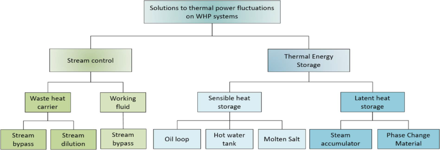
Several studies were conducted to minimise the effect of the flue gases' thermal fluctuations for WHP systems. The resulting suggestions can be classified into two main categories shown in Figure 1:
modifying stream control, which can be implemented to both the waste heat stream and the recovery cycle working fluid stream,
using an intermediate TES system to absorb and damp the thermal fluctuations [11].
Jiménez-Arreola and his co-workers [12] assessed the potential of generating power through an ORC in an off-design operation from fluctuating exhaust gases exiting a steam generator plant. This study compared utilising internal combustion engine (ICE) exhaust gases waste heat in operating an ORC with two candidate evaporator heat exchangers (HEX), double pipe HEX and plate HEX. The results indicated that the double pipe HEX design has twice the heat transfer area as the plate HEX has due to the change in the heat transfer characteristics. Also, they found that when the ICE load is reduced to 60% of the full load, the ORC engine does not respond by the same amount of reduction; it measures 72% of the ORC full load [12]. Nevertheless, utilising temporal source waste heat in a part-load manner without thermal storage will result in inefficient energy conversion and infeasible waste heat recovery.
Another techno-economic analysis was performed for retrofitting an ORC to three industrial waste heat applications that are corresponding to three operational scenarios: (1) hot air exhaust from clinker cooling with temperature fluctuations only, (2) rolling mill reheating furnace exhaust gases with mass-flow fluctuation, and (3) electric arc furnace exhaust gases with both temperature and mass flow fluctuations [13]. The study compared different solutions for each case scenario based on CO2 savings and the Levelized Cost of Electricity (LCOE). With regard to the first case (WHR from clinker cooling), a comparison was considered of integrating an intermediate oil loop, air injection to the source heat, heat source by-pass, latent heat storage using two tanks, and a single sensible heat thermal storage. This comparison suggested that implementing latent heat storage had the highest CO2 savings and the lowest LCOE. As for the rolling mill reheating furnace, only by-passing access mass-flow and two-tank thermal storage were considered. By-passing 75% of the highest mass flow showed better results in terms of CO2 savings. In contrast, the electric arc furnace with both temperature and mass fluctuations, implementing an oil loop without storage, had the best LCOE followed by the two-tank sensible TES. The latent heat TES showed better recovery resulting in higher CO2 savings [13].
An important study of designing and comparing two ORC direct evaporators for a WHR considering the dynamic behaviour of flue gases from a diesel engine was conducted by [14]. The study focused on optimising an ORC evaporator at a design point and its behaviour under the variability of the source considering thermal inertia. Phase change materials (PCM) as a latent heat TES were previously proposed for furnaces having high-temperature fluctuations with quasi-steady mass flow rates, such as electric arc furnaces in [11],[13],[14]. Although, another study proposed using an aluminium alloy based TES to recover a quasi-constant temperature with significant variability in mass flow rate from a reheating furnace [17].
Solutions for thermal power fluctuation suggested by researchers [11]
The TES technology has emerged to be one of the attractive topics for researchers in the last decades due to its potential of contributing to many applications, including renewable technology, industrial WHR, heating & cooling, heat pumps, buildings, and even transportation. TES systems vary in their methods, technologies, functionality, capacities and applications. There are three leading technologies in TES systems: sensible, latent and thermochemical heat storage, each of which has its unique characteristics. For all TES technologies, properties of the materials should be taken into consideration for selection to ensure good performance, durability and safety.
Sensible heat storage is the most mature and widely implemented method compared to other methods due to its simplicity, where the material, either solid or liquid, stores the energy in its specific heat capacity. The materials experience no phase change in this process of heating/cooling, and the materials used in this method are usually water, oils, molten salts, sand, rocks or concrete. The low cost of these materials and their abundant presence allowed it to be the cheapest technology.
Although many investigations were conducted assessing sensible thermal storages, yet there was a lack of studies conducted on industrial waste heat recovery. This is due to several issues associated with sensible heat storage. One of the main issues is that the heat transfer is limited to the specific heat where no phase change occurs to increase the capacity of the heat absorbed by the material; thus, large heat storages are required. Another issue is that although fluctuation of the power is decreased, the temperature outlet of the sensible TES is usually dynamic, especially in high fluctuation input. Furthermore, processes such as heating furnaces have high-temperature ranges, which can limit candidate materials.
Several research papers studied temporal waste heat recovery from industrial processes by integrating TES of several technologies. A study proposed a novel mathematical model for simulating transient conditions in a concrete passive sensible TES that shows alignment with experimental data within 2% of error [18]. Another study provided experimental and computational analysis for a packed-bed TES to recover waste heat up to 525 °C at an industrial scale [19]. Moreover, a practical case study of a multi-product batch process in a textile plant investigated both a direct heat recovery using pinch point analysis as well as an indirect heat recovery [20]. The indirect heat recovery proposed consisted of using a closed intermediate loop and heat storage. This method enabled the recovery of 5% of the total energy consumed daily in the plant.
Reverberatory gas-fired furnaces, as shown in Figure 2, are common in the aluminium industry for remelting and metal holding, and alloying.
Reverberatory gas-fired metal holding furnace
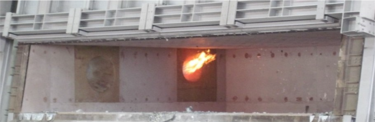
Fuel and air are supplied to the furnace burners within 510% of excess air for complete combustion. There are mainly two types of burners used in reverberatory gas-fired furnaces, standard cold-air burners or regenerative burners. Although the regenerative burners are more efficient than the former, using them for insufficient loads will result in inefficient performance [21].
Standard reverberatory gas-fired remelting furnaces expel about 3050% of their high-quality energy through the chimney [22]. Figure 3 illustrates the heat flow schematic in a typical molten-metal holding furnace.
Energy losses in a reverberatory remelting furnace
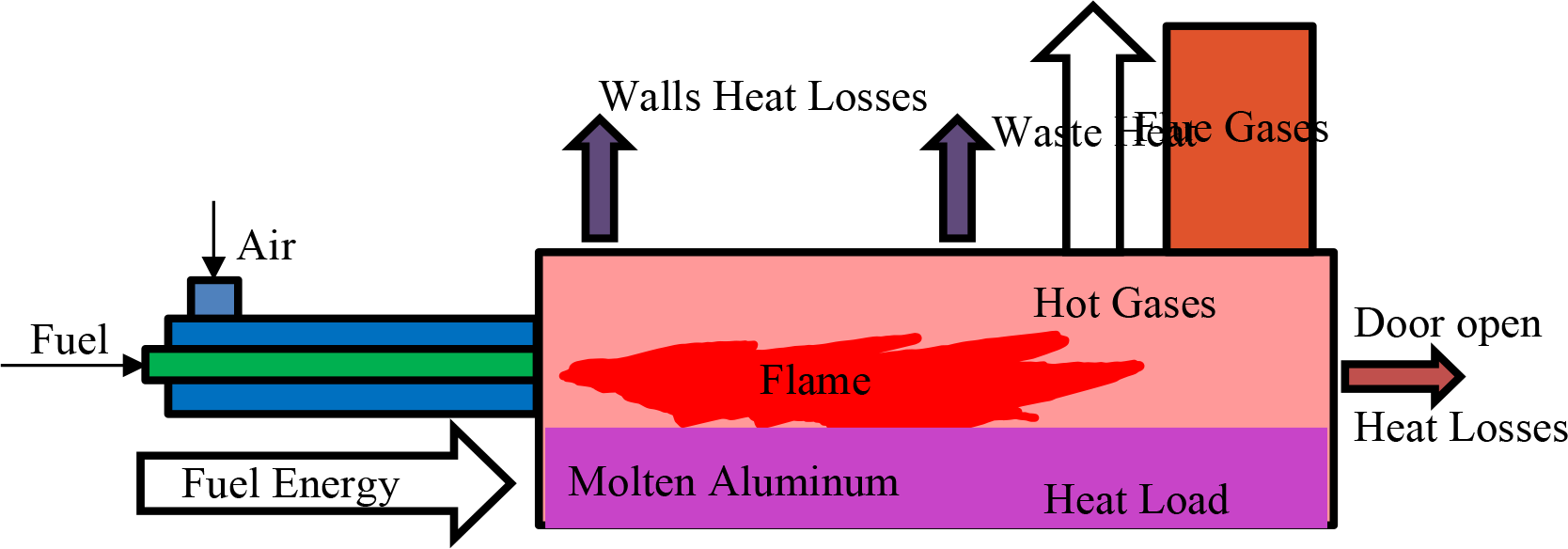
The main source of energy comes from the combustion of fuel which is natural gas in this case, and the molten metal consumes a small portion of the total energy to keep the metal in its molten condition at a specific set point. The rest of the input fuel energy will leave the furnace as waste heat through the furnace walls, frequent door opening and flue gases. Flue gases leave the furnace at a temperature around 700 ?C before they get cooled by entrained cold air. The flue gas waste heat has high energy potential because of its high temperature. The number of burners and their loads depends on the furnace metal-batch capacity and the main task: melting, holding, and alloying.
Temporal flow and temperature measurements for three furnaces over a single batch
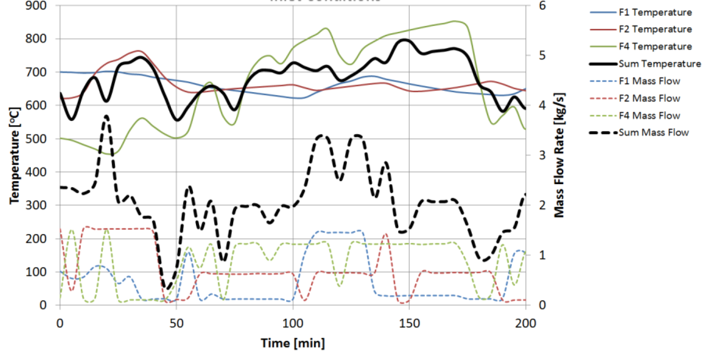
The furnace operation is controlled by a feedback control system that receives a set-point temperature from the metal thermocouple, located 60 cm below the metal surface, to switch the flame of the burner on and off. Therefore, the measured flue gas flow rate and the temperature vary with time, as shown in Figure 4 for three furnaces, F1, F2, and F3. The exhaust gas temperature and species concentration measurements are taken from a tab located between the furnace and its chimney exit before it mixes with the atmospheric air.
This study considers flue gases collected from three aluminium-holding furnaces operated in batch mode. Several fluctuation management techniques are implemented to determine the best alternative in achieving a smooth output of waste heat that includes: (1) an optimisation model of scheduling a time shift between batches, (2) temporal cold-air injection to the flue gas, and (3) integrating sensible thermal storage. The heat output will be used to model an ORC and RO plant to utilise the excess heat for power and water production. Also, the analysis will be extended to include the utilisation of remelting furnaces. This approach provides the following contributions:
Assessment of the potential energy recovery in aluminium reverberatory furnaces.
A novel approach of reducing input fluctuations through optimisation modelling.
Investigating the most suitable alternatives for the temporal waste heat recovery.
Assessment of the potential of power and water generation from aluminium industry waste heat.
Assessment of the appropriate material for the TES used to recover waste heat.
This study investigates the best approach among three proposed techniques to provide steady-state thermal energy out of a transient waste heat source. This is done to assess the potential of recovering waste heat from holding and remelting reverberatory furnaces to produce electricity and water. Temporal flue gas temperature and mass flow rate are measured on site, as shown in Figure 4. These measurements are fed to three developed models for the three proposed techniques of damping the waste heat fluctuation, including (1) Particle Swarm Optimization (PSO) model, (2) hot/cold flow stream mixing temporal model, and (3) transient computational fluid dynamics (CFD) model. The concept of the sensible TES is chosen due to its maturity and reliability, as well as it is most suited for the high energy fluctuations that are present in the processes.
Flow diagram of the waste heat recovery system for holding furnaces.
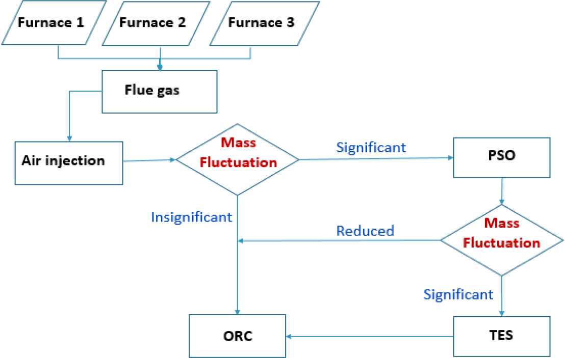
Figure 5 shows the flow diagram of the proposed techniques methods order. The first path is to assess the furnaces flue gas exergy using thermodynamic exergy analysis to evaluate the potential feasible work. Three furnaces flue gas mass-flow rates and temperatures data are collected in Excel sheet and made as an input file for the three techniques models. The first model is a flow mixing thermodynamics model using the IPSEpro interface. The two inputs are the flue gas data sheet and a temporal cold air stream that will lower the maximum peak temperature and increase the total mass flow rate. If the resultant flow does not damp fluctuations of both mass flow and temperature, then the next technique will be implemented and so on, until it satisfies the ORC best operation condition and produces the most out of the flue gas potential work.
The following subsections will describe the three methods governing equations as well as assumptions and boundary conditions.
Flue gas exergy code is written on MATLAB to estimate the maximum available work that can be delivered at the dead state condition where the aluminium plant is located. The total exergy flow is calculated based on the measured flue temperature and flow rate collected from three metal holding furnaces. If temperature and flow rates are varied, as shown in Figure 3, then exergy is varied accordingly.
The specific exergy for steady-state steady flow (SSSF), where kinetic and potential energies are neglected, can be expressed as:
(1)
This is the maximum available work per unit mass that can be produced by a flow at temperature T and dumped to a dead state at temperature To[K]. The specific enthalpy h and specific entropy s are dynamically calculated using the measured heat source temperature. The total exergy flow is:
(2)
As it can be seen from this equation, the resultant exergy fluctuation will be even higher than each term in the equation due to the multiplication.
The collected stream of flue gas has high variability in temperature as well as mass flow. In this assessment, the stream is injected with cold air to help cooling the stream to suit the ORC as well as observing the stream output in terms of mass flow. The stable temperature and mass flow will enable to utilise the waste heat directly to generate power by the ORC. This can be done through a control system that measures the amount of air required to reach a specific temperature. Air injection will reduce the maximum temperature; however, it will not reduce the fluctuation significantly. The fluctuated flue gas flow rate will mix with a fluctuated cold air stream that maintains the total amount of energy with lower quality because of the low average temperature of the resultant mixture of hot and cold flow streams.
The main goal of this method is to optimise the operation time shift between a cluster of three furnaces to generate a total temporal flue gas flow rate and temperature that is much smoother than a single furnace. It is possible to minimise either the standard deviation or the difference between the peaks amplitudes of the total fluctuated signal. This method is novel, and up to the knowledge of the authors, it has not been studied so far. The particle swarm optimisation (PSO) algorithm is one of the candidate methods for such optimisation because of its feature and applicability in similar power-and energy-related techniques, as explained in the following paragraphs. The expected output of this algorithm is to answer this question: what is the best operation time-shift among the three furnaces to get the most smoothed results?
PSO is considered one of the evolutionary algorithms based on artificial intelligence; therefore, it is widely applied in engineering and scientific research [23]. The PSO was already implemented in the field of power generation, and power systems accounting for 5.8% of the total PSO applications with more than 39 papers were published [17], [18]. The concept of this model is inspired by the phenomena of a bird flock flying in search of food where each particle position corresponds to a possible solution, and thereby, a flock of "n" particles will iterate and move in search of an optimal solution. The conditions of the particles are altered in the influence of three factors: the own particle inertia, the particle's most optimal position, the swarm's most optimal position [26]. The following equations change the position and speed of a particle:
(3)
(4)
where: and are the velocity and position of the ith particle, with d and k indicating the dimension and iteration, respectively; pbest and gbest represent the personal best position and the global best position. Among the constants that regulate the equation in terms of particle movements, w represents the inertia of particles attained in the previous position, while c1 and c2 are the acceleration constants and are set to be 2 in most applications. Also, and represent random numbers in the range of 0 to 1 [23]. Therefore, applying this method will explore the optimum operating time delay between the furnaces by trying two objective functions at a time: minimising the standard deviation and minimising the difference between the lower and the higher peaks value. Therefore, applying the PSO model will be the most suitable as it enables exploring the optimum operating-time shift between furnaces. It will be performed by shifting the input profiles in a systematic and directed manner instead of the genetic algorithm that is based on altering several variables each iteration in a semi-randomised manner. The set-up of the model is summarised in Table 1. The algorithm code is developed on MATLAB.
PSO model set-up
| Objective function | Minimise standard Deviation | Minimise high/low peak difference |
|---|---|---|
| Constraints | Unbounded | Unbounded |
| Maximum iterations | 5000 | 10000 |
| No. of particles | 100 | 100 |
| Dimensions | 2 | 2 |
The main objective of the computation fluid dynamic (CFD) modelling is to investigate and design the appropriate sensible TES solid structure that will be able to diffuse the waste heat fluctuation in the solid structure and produce uniform temperature. This solid structure comprises a solid block that has the flue gas and HTF running in tubes installed in it. The solid block must be semi-infinite enough with the appropriate thermal diffusivity transport phenomena to damp the dynamic waste heat components provided by the flue gas tubes to a uniform temperature before it reaches the HTF tubes. Therefore, the sizes of the solid block, flue gas tubes, HTF tubes, and the distance between tubes as well as the solid thermal diffusivity, must be investigated and optimised to maximise the gain of heat recovery. Obviously, it is a complex engineering problem that can be investigated either experimentally or using a sophisticated CFD model. The experimental investigation is significantly expensive and exhaustive, not only cost-wise but also time-wise. The availability of a high-speed computing cluster allows us to develop several CFD models to reach the appropriate TES block design.
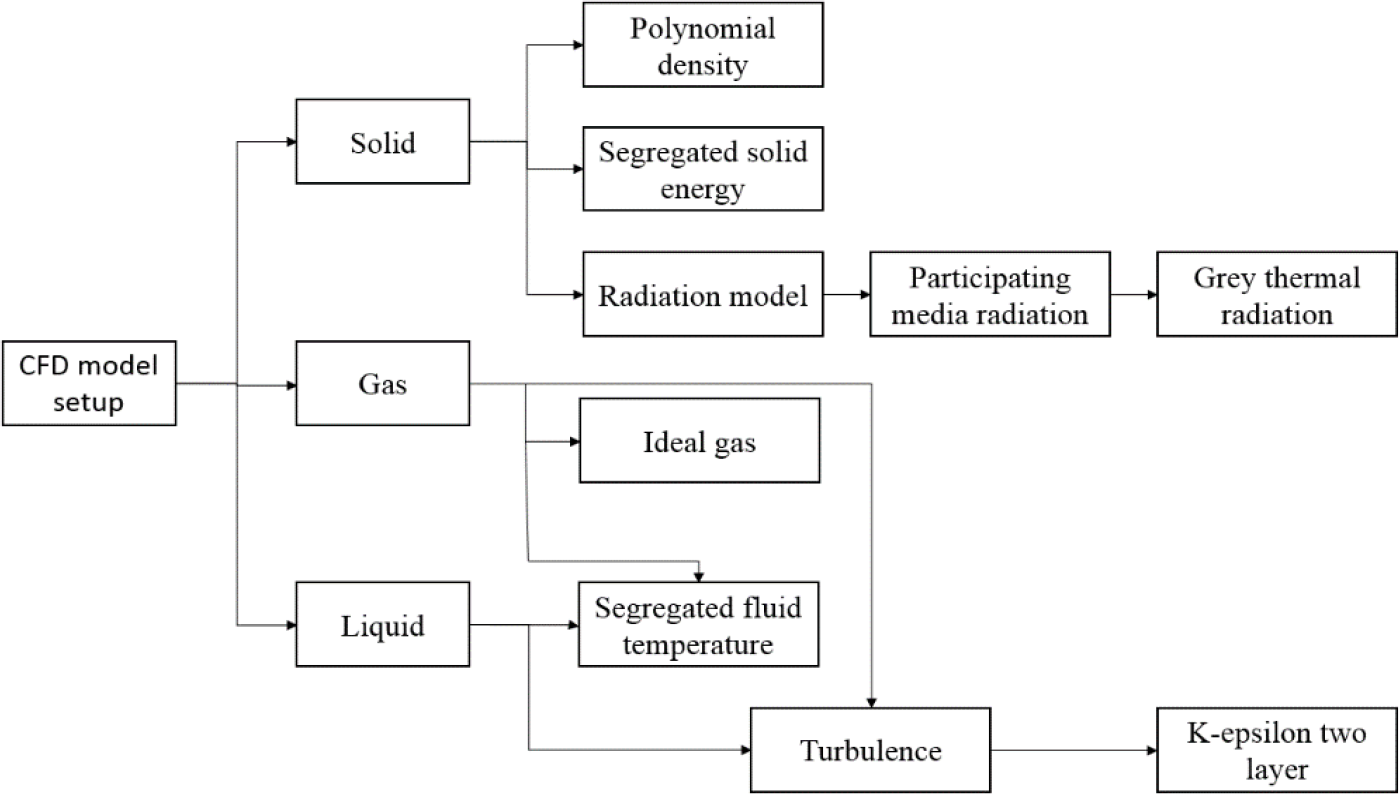
3D transient CFD model was developed on STARCCM+ platform. As shown in Table 2, the appropriate physics is implemented to simulate the fluid flow and heat transfer governed by the laws of mass, momentum, and energy conservation equations (5)(8). These physical laws include fluid flow turbulence, heat conduction, convection and radiation. In addition, an implicit transient time step was used for the transient simulations. Cylindrical coordinates (r,θ, z) are used to describe the continuity, momentum and energy equations for the flow running in the tubes. Cartesian coordinates (x,y,z) are used to describe the transient conduction heat transfer in the solid block. The following are the mathematical representations of the governing equations; where the mass and momentum equations are presented respectively:
(5)
(6)
where denotes gravity acceleration. The stress tensor is given by:
(7)
where I is the unit tensor, and:
(8)
where ∅ is the viscous dissipation function.
The energy equation of the heat transfer in the solid block is given by:
(9)
Certain boundary and initial conditions are assigned in the three computational domains, solid block, flue gas tubes and oil tubes to solve the mathematical problem. As for the momentum equation, the no-slip condition is set on the tubes' boundaries. For the TES solid block, adiabatic walls were applied on the wall's boundaries. Furthermore, the thermal properties of the solid blocks were evaluated based on both the literature [27] and the thermophysical database JMatPro. As for HTF, a commercial fluid Dowtherm A was used, and the thermal properties were evaluated based on the datasheet provided by the oil manufacturer [20], [21]. Table 2 and Figure 6 summarise the specifications and properties of the modelling set-up.
Summary of the model set-up
| Physics | Model |
|---|---|
| Dimensions | 3D |
| Time | Implicit transient model |
| Energy | Segregated flow and solid energy |
| Equation of state | Ideal gas |
| Turbulent | κ-ε, Reynolds-averaged Navier-Stokes, realisable κ-ε, two layers, exact wall distance, two layers all y+ wall treatment |
| Radiation | Surface to surface, gray |
| Fluid properties | Vary with temperature |
| Solid properties | Vary with temperature |
| Walls | No-slip condition and zero-resistance contact on the fluid domain tubes, and adiabatic walls on the solid block |
| Mesh | Polyhedral – finite volume |
| Mesh cells | 1.3 to 20 million |
| Prism | 2 prism layers with 1.1 expansion rate |
CFD sub-model setup
Regarding the accuracy and stability of the developed models, a sensitivity analysis was conducted with three mesh sizes to ensure mesh size independence. In addition, in the transient models, a sensitivity analysis was conducted on the number of iterations for each time step as well as varying the time step for the simulations to prove that the results are independent of the solving time resolution.
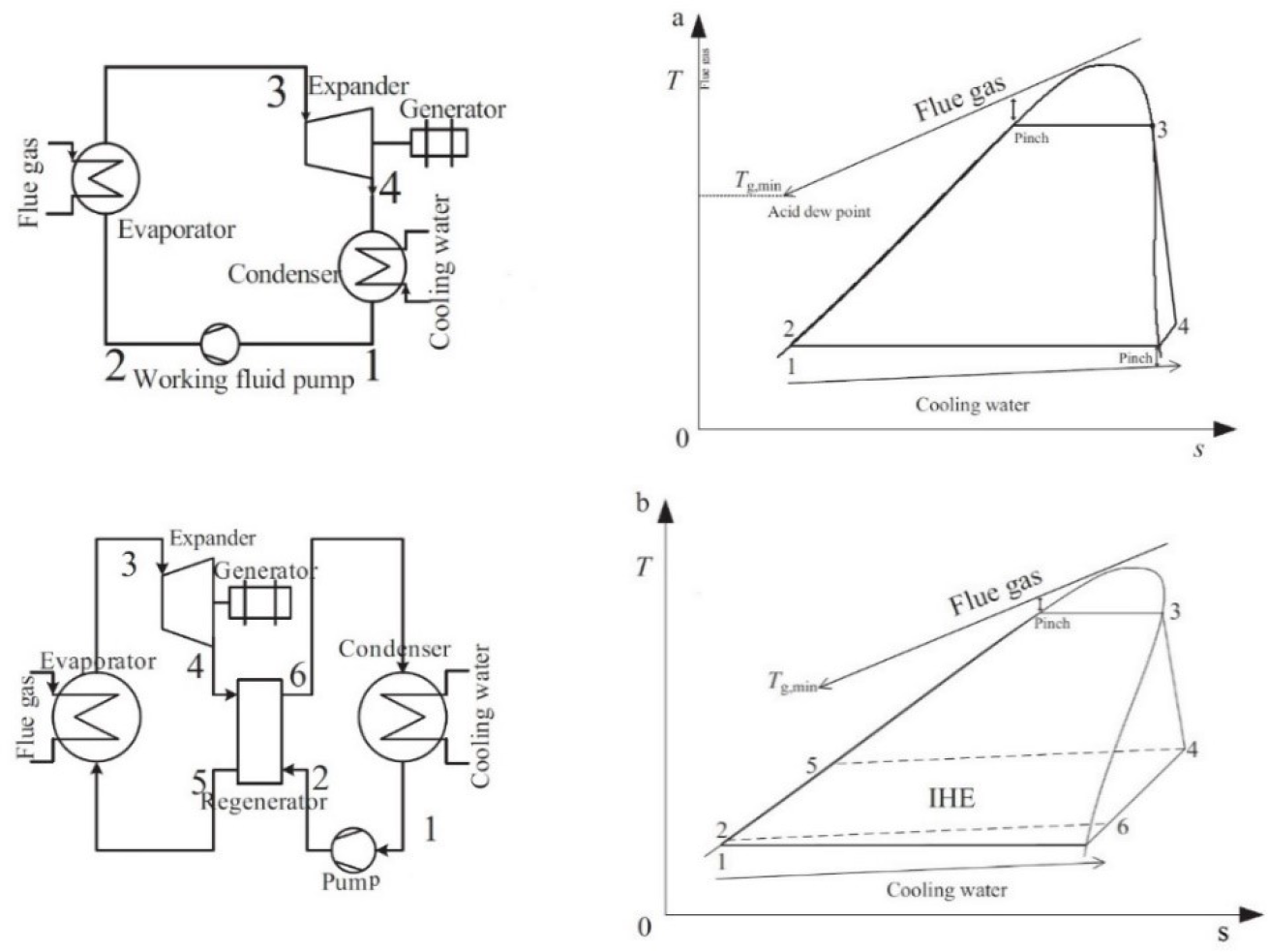
Organic Rankine cycle (ORC) is used to convert the flue gas waste energy into useful electricity. The TES medium is required to damp the flue gas energy fluctuation and smoothly operate the ORC. The produced electricity can be used to operate the reverse osmosis (RO) plant to supply the cast-house with the desalinated water required for direct chill (DC) casting mould. After implementing the three models of ORC using IPSEpro software, the efficiencies and output power were the highest when isopentane was used as the working fluid, and a recuperate heat exchanger was added. Figure 7a shows a layout of a simple ORC with its corresponding Ts state. The liquid fluid is first compressed by a pump from state 1 to 2 and after that, evaporated by the heat source from state 2 to 3, reaching to saturated vapour. The saturated vapour goes through an expander in which a shaft is driven to generate power from stage 34. Finally, the exhaust vapour goes through a heat sink (mainly a water-cooled condenser) in stage 41. Another configuration is shown in Figure 7b, which uses a heat exchanger to preheat the stream coming out of the pump in stage 25 by utilising the exhaust heat exiting of the expander in stage 46.
Layout of: simple ORC (a) and recuperated ORC (b)
The mass balance of the ORC components is given by:
(10)
and the energy balance is given by:
(11a)
For the ORC cycle:
(11b)
The thermal efficiency is the ratio of the net power output to the input heat rate which can be expressed by:
(12)
The RO is a process of water desalination based on membrane technology where the membrane allows water molecules to penetrate and blocks the salts from entering. This is done using the high-pressure flow of water supplied by powerful pumps, and this process can be expressed by the equations below.
Mass/volume balance:
(13)
Salt balance:
(14)
Salt rejection:
(15)
Specific power consumption:
(16)
where: V is the volume, S is the salt concentration, and subscripts f, p, b denote feed, permeate, and brine, respectively.
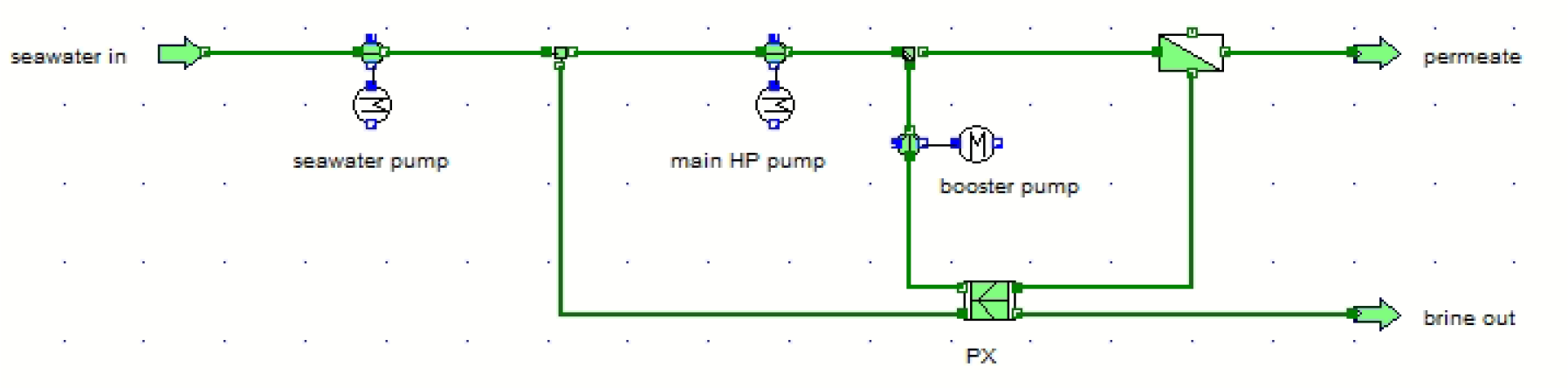
Figure 8 shows the schematic of the RO plant equipped with an energy recovery component that recovers the pressure of the brine to be used in the feed water stream based on positive displacement.
RO water desalination plant for waste heat recovery
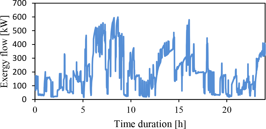
By using eq. (1), the exergy of the flow is calculated through a MATLAB code for 24-hour duration. Figure 9 shows the severe variation in exergy due to the mass flow and temperature fluctuations. The average exergy of the flow from the three furnaces is 195 kW, whereas the minimum and maximum exergy flows are 15 kW and 600 kW, respectively. These values give an insight into the scale of the WHR system that can be applied. However, if the study was to be scaled up to include all the 18 holding furnaces available in the plant's cast-house, then the system could recover more heat from an average of 3.5 MW. In addition, utilising waste heat from the remelting furnaces has a higher potential for heat recovery due to the substantial amount of energy required for melting scrap metals. It is estimated to have 20 times more exergy than holding furnaces.
Exergy flow of three furnaces for 24 hour operation
One of the solutions suggested in the literature was to mix the flue gas stream with air to supply a constant temperature. Therefore, this method was applied, and the effect on the mass flow rate was observed.
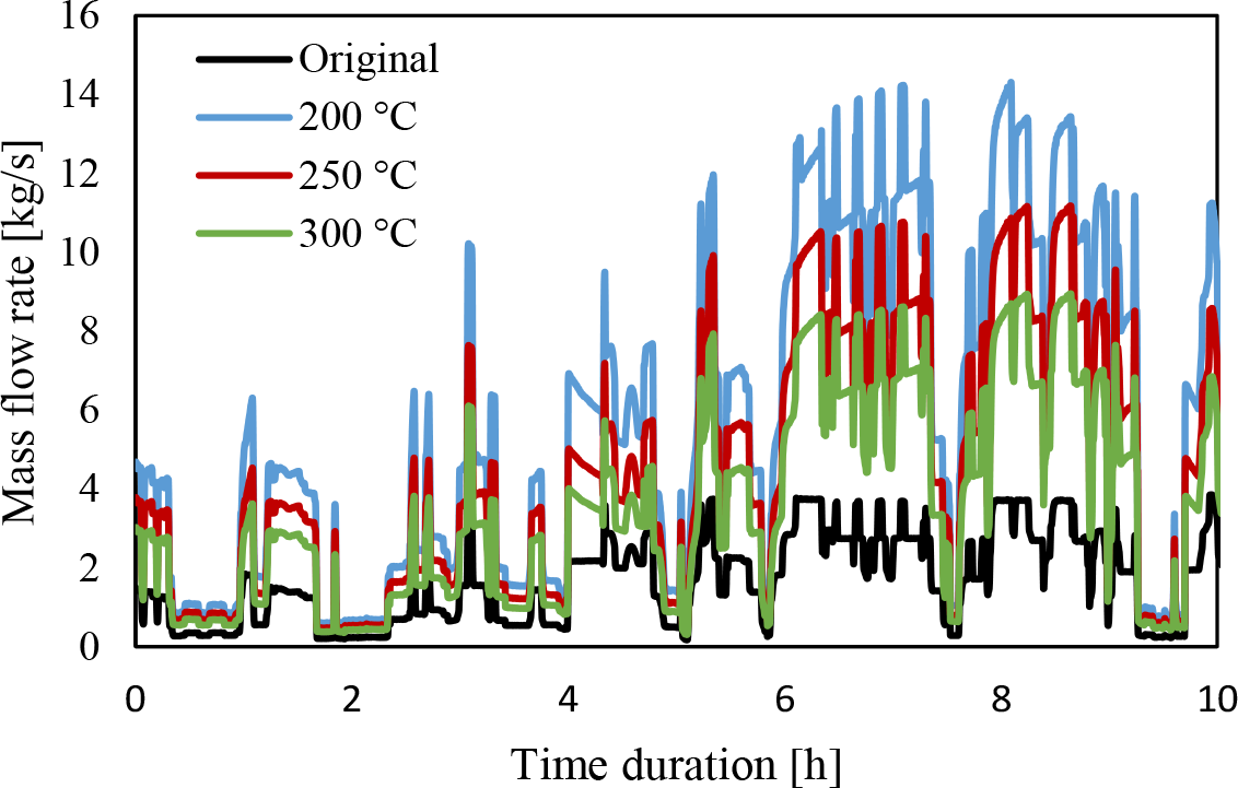
Figure 10 presents the effect of injecting fresh air into the exhaust gases that are collected from the three furnaces. The transient mixing model is set for two input streams (hot gases from the furnaces with the given temporal mass flow and temperature profiles and cold air stream with unknown mass flow rate) and one output stream of constant temperature and unknown mass flow rate. The cold air mass flow rates are calculated to achieve the constant outlet temperatures of 200 °C, 250 °C, and 300 °C, as shown in Figure 10. Although the stream reached a constant temperature, it can be noticed that the temperature fluctuation translated to a significant increase in mass flow rate fluctuation. Moreover, increasing the temperature of the mixture stream will result in less oscillation; however, the mixture stream mass flow profile is about six times the original one. This temporal variation will hinder the possibility of utilising the direct stream to run an ORC in a consistent full load mode. Also, a further rise in the outlet temperature to lower the fluctuation will not suit the idea of ORC due to its source temperature limitation.
Effect of air injection on stream mass flow rate
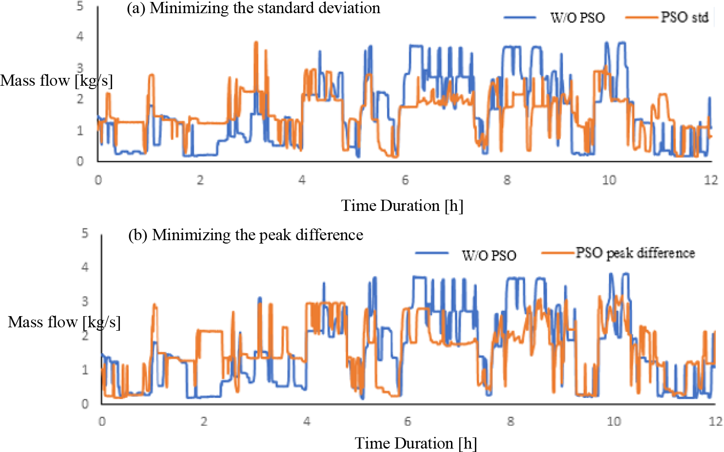
After implementing the PSO on the three furnaces mass flow rates, results showed an improved overall output when choosing the standard deviation as an unbounded objective function to be minimised. The standard deviation value was 0.96 under normal operation; however, it is reduced to an optimum value equal to 0.7 when using the optimisation model. Figure 11 shows the comparison between the normal operation and the optimised operation for 12 hours. Despite the significant reduction in the overall fluctuation, the optimised mass flow rate profile increased the fluctuation in the timing between the second and the fourth hour of operation, as shown in Figure 11a. Changing the objective function to minimise the difference between the maximum and minimum amplitudes throughout the operation did not show any better results in eliminating the fluctuations, as shown in Figure 11b. Nevertheless, the difference between the global maximum and minimum mass flow amplitudes is reduced from 3.7 kg/s to 3.1 kg/s with much less occurrence than the occurrence of the 3.7 kg/s amplitude, thus, reducing the overall fluctuations in the mass flow rate.
Results of the PSO for: minimising standard deviation (a), minimising peak difference (b)
Furthermore, in many industries delaying and scheduling the operation hours between the furnaces seems impractical because it is difficult to comply with the day to day schedule. This might introduce further complications in the production process since the holding process is related to the rate of alumina reduction in the potline before the casting process. However, increasing the number of furnaces to the model for scaling up the waste heat recovery will indeed decrease the fluctuations significantly as opposed to regular operations. Integrating a sensible thermal storage block proves to be a good solution for damping the temporal fluctuations of temperature and mass flow together. There are several TES technologies; sensible heat, latent heat, and thermochemical. Both latent and thermochemical TES technologies are costly and are still in laboratory testing. In addition, latent and thermochemical TES require charging and discharging heat that is heavily dependent on consistent temperature profiles with a high and low phase manner. Therefore, sensible heat TES is selected for this study.
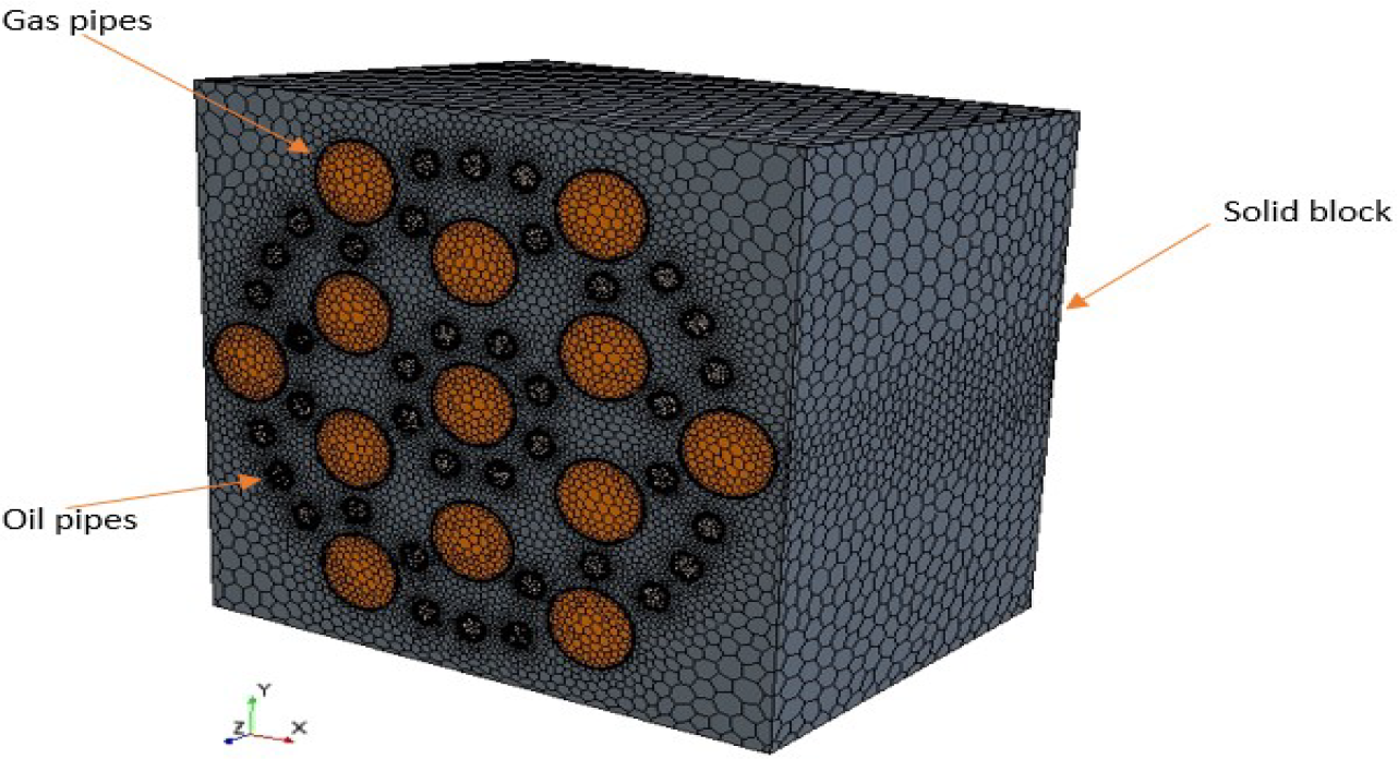
Figure 12 shows the layout of the sensible TES, where it consists of a solid block of 2×2×1.6 m with 30 cm and 5 cm diameter of gas and oil pipes, respectively. The gas enters the pipes with transient mass flow and temperature, transferring the energy to the solid block that acts as a thermal-waves damping medium, thereby transferring smooth energy to a counter-flow HTF.
The geometry of the sensible TES
Cross-section of the TES for: cast iron (a), concrete (b), aluminium (c)
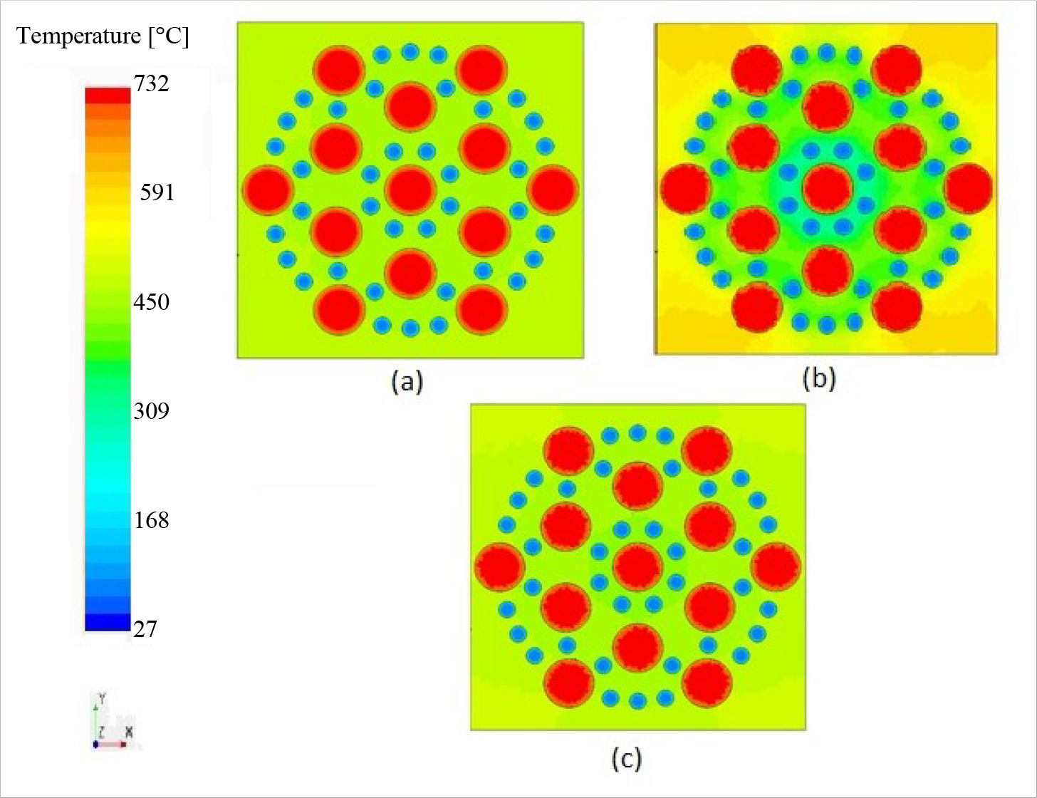
Figure 13 shows a cross-sectional front view of the middle of the TES block for the three candidate materials, cast iron, concrete and aluminium, in a steady-state model. The temperature of the flue gas and the HTF entering the block was 727 °C and 40 °C, respectively. From the contours below, it is noticed that both the cast iron and the aluminium block had a better temperature distribution due to their high thermal conductivity compared to concrete. Nevertheless, in terms of the outlet HTF temperature, both cast iron and aluminium solid blocks were identical with a temperature of 163 °C which is slightly higher than the outlet HTF temperature in case of using a concrete block, 153 °C.
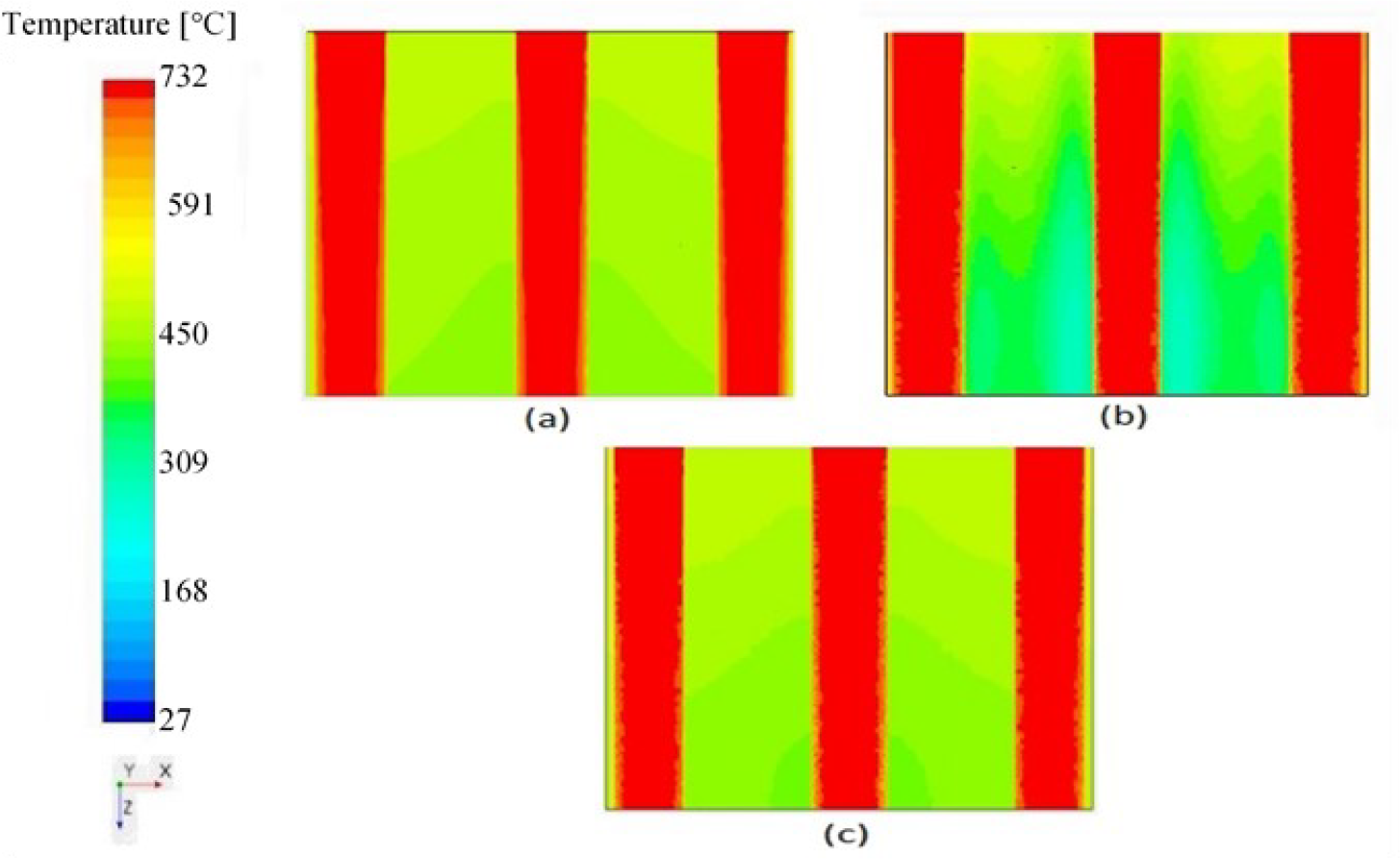
Figure 14 shows a vertical cross-section of the TES of the same simulation; the vertical red tubes show the flue gas pipes, whereas the green areas show the block temperatures. The flue gas flows from the top to the bottom, noticing barely any reduction of the temperatures. However, a slight change is more visible in the flue gas pipes around the edges in Figure 14c and better temperature distribution in the block. On the other hand, in Figures 13b and 14b, a low temperature is noticed in the middle of the block due to the heat absorbed by the oil pipes concentrated in the middle while high temperatures on the solid block sides and corners. Thus, accumulated heat is present within the block due to the low thermal conductivity of the concrete, as shown in Figure 13 and Figure 14. In this case, the solid block will act as thermal storage when the flue gas has high temperature and mass flow peaks. The accumulated heat will be dispatched to the HTF when the flue gas fluctuates to the low temperature and mass flow peaks. Therefore, enhancing the distribution of the oil pipes in the concrete block is suggested as very important to dispatch the stored heat effectively.
Vertical cross-section of the TES: cast iron (a), concrete (b), aluminium (c)
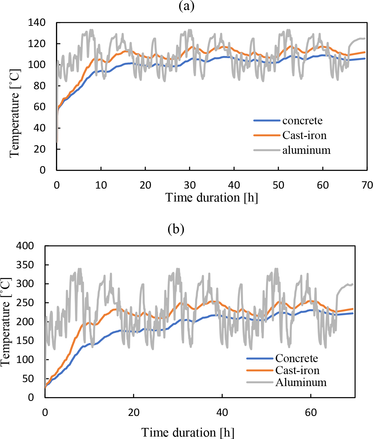
Running the models with the transient condition was also conducted for the candidate materials to observe the effect on the outlet HTF temperatures and examine the effectiveness of the fluctuation damping. Figure 15 shows the average block temperature and the outlet temperature in the three suggested materials with operating furnaces for three days. Results show lower outlet temperatures compared with the previous steady-state operations due to the transient energy input for cast iron, concrete, and aluminium with an average temperature of 107 °C, 100 °C, and 110 °C, respectively. Although cast iron and aluminium have similar average temperatures, it can be noticed that the aluminium block did not serve the purpose of damping the temperature of the HTF due to its lower specific heat capacity. In addition, the temperature difference between the cast-iron block and the concrete block after one day of operation decreases, giving it a slighter advantage of cast iron over concrete. Nevertheless, this small difference would not justify using cast iron due to its higher density and cost, not to mention the difficulties of large block casting and transportation challenges. Therefore using the concrete block is the most suitable for this purpose. It is also important to note that the high-temperature difference between the block and the hot and cold fluids suggests an optimisation among the number, size, and distribution of the flue gas and HTF tubes in the solid block. Furthermore, changing the pipe distribution to allow multi-pass flow in the block will surely increase the temperature to the desired output and allow further recovery of the flue gas.
Considering this above, designing a sensible TES with high temperatures can be achieved to operate an ORC in smooth conditions with a consistent energy transformation. Therefore, the input was scaled up to recover the waste heat from 18 standard furnaces and exchange the heat via a sensible TES to the HTF, which in return enters an evaporator to heat the ORC working fluid. From the ORC thermodynamic model, a net power output of 86 kW is achievable from the holding furnace using the refrigerant R245fa as a working fluid, as suggested from the literature [30], with a maximum efficiency of 12.6%. However, utilising the same number on the remelting furnaces can be estimated to produce 323 kW with an efficiency of 13.6% with the operating condition mentioned in Table 3.
Mass average temperature of the blocks (a); outlet HTF temperature of TES (b)
The work output can be used to power a RO plant. In parallel, the cooling water from the ORC condenser could be used in a multi-stage flash (MSF) to produce freshwater from the remaining hot flue gas. The power output is sufficient to operate an RO plant equipped with an energy recovery component that recovers waste heat from the brine with a feeding mass flow of 17/70 kg/s of seawater to produce 648/2419 m3 per day of freshwater. This amount of water can be utilised for the casting process saving up to 533/2000 metric tons of CO2 emissions annually in the case house for both the holding and remelting furnaces, respectively. As for the MSF plant, increasing the temperature of the cooling water of ORC to preheat the feed water would require increasing the outlet pressure of the turbine to avoid temperature cross-over in the condenser. As the power output would be reduced, the utilisation of the remaining waste heat could only produce 43.2 m3 per day for the remelting furnaces. Therefore, integrating an MSF plant is infeasible.
ORC operating conditions
| Parameter | Holding furnaces | Melting furnaces |
|---|---|---|
| Net power outlet [kW] | 86 | 323 |
| Thermal efficiency | 12.6% | 13.6% |
| Maximum pressure [bar] | 16 | 20 |
| Turbine inlet temperature [°C] | 120 | 180 |
| Condenser pressure [bar] | 2 | 1.2 |
| Working fluid | R245fa | Iso-pentane |
| Working fluid mass flow rate [kg/s] | 3 | 4 |
| HTF oil mass flow rate [kg/s] | 6 | 6 |
| Maximum HTF temperature [°C] | 150 | 250 |
| Condenser outlet water temperature [°C] | 32 | 31 |
| Ambient temperature [°C] | 25 | 25 |
| Turbine efficiency | 75% | 75% |
| Pump efficiency | 65% | 65% |
| Recuperator | Yes | No |
Effect of oil temperature on power output and the distillate mass flow rate
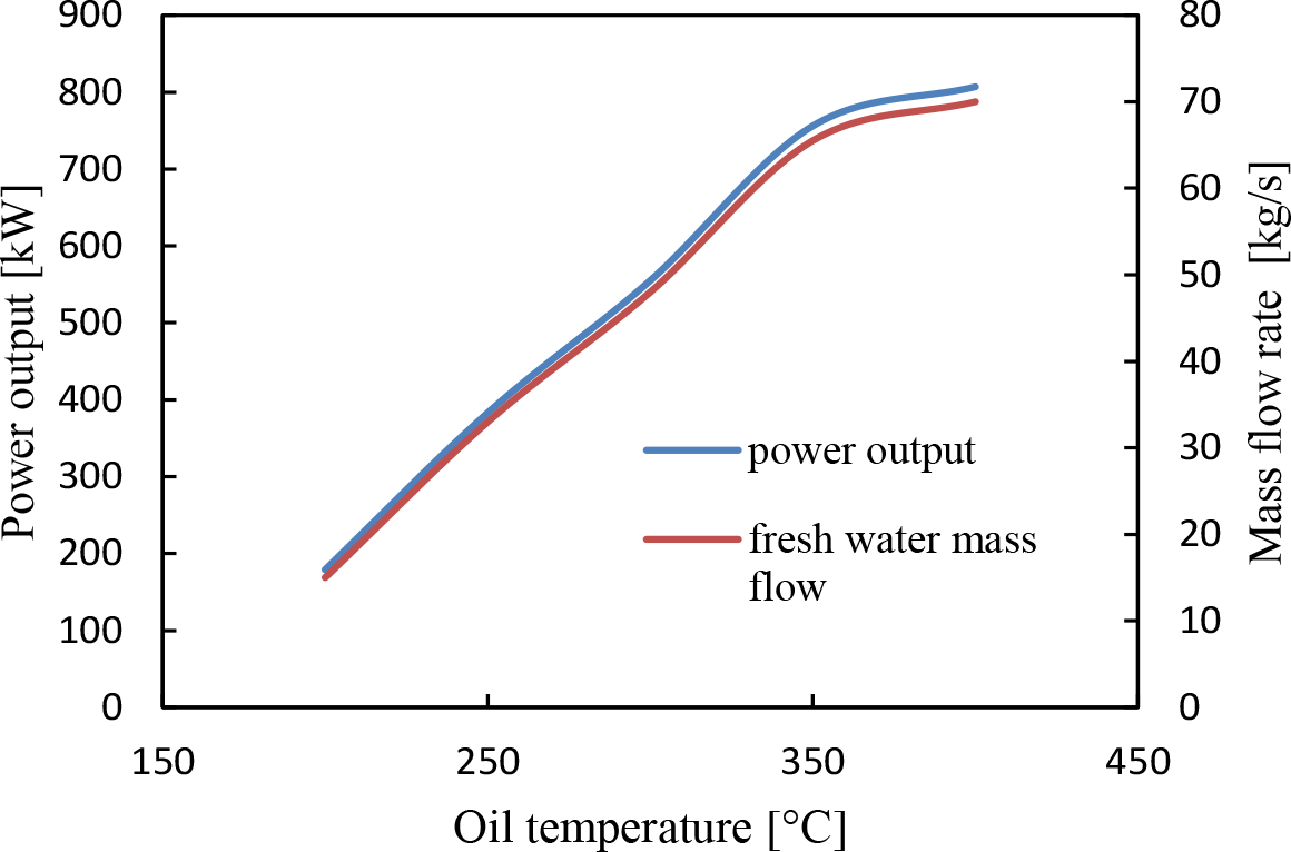
Since the oil outlet temperature in remelting furnaces was assumed to be 250 °C, it is important to predict the effect of varying the oil temperature on the power output and the quantity of distillate water. Therefore, Figure 16 shows the results of varying the inlet oil temperature from the minimum achievable value to the maximum safe value of operation on both the power output and the distillate mass flow rate. The results of both the power and mass flow rate of the distillate have an identical linear profile up to HTF temperature of 350 ?C. Above that temperature, the rate of change in the output starts to decrease significantly. Achieving a temperature ranging between 250 °C and 350 °C is possible by enlarging the thermal storage block; however, it will be challenging and infeasible beyond this range.
Various energy-transport fluctuation management techniques had been studied on the holding and remelting aluminium reverberatory furnaces waste heat recovery, including air injection, oil-loop, sensible TES, and time delay optimisation model. These techniques were examined to produce smoother waste heat recovery to generate electric power for use in an RO plant to produce the freshwater required to operate the cast-house casting processes. In the optimisation model, the time delay between the furnaces' operating hours was applied among three holding furnaces to supply uniform waste heat recovery. This optimisation process has relatively reduced the fluctuation in the mass flow rate and potentially provides smoother results when applied to cover many furnaces.
Furthermore, this study revealed that sensible TES was the least challenging solution among the three investigated methods. Cast iron and solid concrete blocks were preferable to damp the fluctuations of the flue gases where concrete proves to be more favourable in terms of cost, reliability, and fabrication. The calculation showed that utilising waste heat from 18 melting furnaces can produce 2419 m3 per day of freshwater to supply the cast-house facility from RO desalination powered by the output electricity of the ORC unit, cutting 2000 metric tons of CO2 emissions annually.
The results of the TES can be improved by considering several factors, such as increasing the surface area of the fluid running tubes to enhance the heat transfer rate by using multi-pass thermal storage. In addition, developing composite materials that would enhance the specific heat and the thermal conductivity of the storage medium must be further investigated. Lastly, for future investigation, an economic analysis is needed to assess the cost-effectiveness of the project.
- ,
Energy Technology Perspectives 2017 - Executive Summary ,Iea ,pp 371 , 2017, https://doi.org/10.1787/energy_tech-2014-en - ,
Aluminum Association of Canada , https://aluminium.ca/développement-durable/l?aluminium-et-l?énergie - ,
An overview of opportunities for waste heat recovery and thermal integration in the primary aluminum industry ,Jom , Vol. 64 (8),pp 990996 , 2012, https://doi.org/10.1007/s11837-012-0367-4 - ,
Potential energy savings by application of the novel CRIMSON aluminium casting process ,Appl. Energy , Vol. 89 (1),pp 111116 , 2012, https://doi.org/10.1016/j.apenergy.2010.12.029 - ,
ETEKINA: Analysis of the potential for waste heat recovery in three sectors: Aluminium low pressure die casting, steel sector and ceramic tiles manufacturing sector ,Int. J. Thermofluids , Vol. 12 ,pp 100002 , 2020, https://doi.org/10.1016/j.ijft.2019.100002 - , , Light Metals 2016, 2016
- , , Light Metals 2016, 2016
- ,
Complex and Efficient Waste Heat Recovery System in Aluminum Foundry ,Energy Procedia , Vol. 112 ,pp 504509 , 2017, https://doi.org/10.1016/j.egypro.2017.03.1134 - ,
Industrial waste heat recovery technologies: An economic analysis of heat transformation technologies ,Appl. Energy , Vol. 151 ,pp 157167 , 2015, https://doi.org/10.1016/j.apenergy.2015.01.147 - ,
The aluminium industry: A review on state-of-the-art technologies, environmental impacts and possibilities for waste heat recovery ,Int. J. Thermofluids , Vol. 12 ,pp 100007 , 2020, https://doi.org/10.1016/j.ijft.2019.100007 - ,
Thermal power fluctuations in waste heat to power systems: An overview on the challenges and current solutions ,Appl. Therm. Eng. , Vol. 134 (November 2017),pp 576584 , 2018, https://doi.org/10.1016/j.applthermaleng.2018.02.033 - ,
Off-design performance analysis of organic Rankine cycle using real operation data from a heat source plant ,Energy Convers. Manag. , Vol. 133 ,pp 284291 , 2017, https://doi.org/10.1016/j.enconman.2016.12.016 - ,
Techno-Economic Analysis of Waste Heat Recovery with ORC from Fluctuating Industrial Sources ,Energy Procedia , Vol. 129 ,pp 503510 , 2017, https://doi.org/10.1016/j.egypro.2017.09.170 - ,
Analysis and comparison of dynamic behavior of heat exchangers for direct evaporation in ORC waste heat recovery applications from fluctuating sources ,Appl. Energy , Vol. 216 (January),pp 724740 , 2018, https://doi.org/10.1016/j.apenergy.2018.01.085 - ,
Enhancing energy recovery in the steel industry: Matching continuous charge with off-gas variability smoothing ,Energy Convers. Manag. , Vol. 104 ,pp 7889 , 2015, https://doi.org/10.1016/j.enconman.2015.05.012 - ,
PCM-based energy recovery from electric arc furnaces ,Appl. Energy , Vol. 136 ,pp 947955 , 2014, https://doi.org/10.1016/j.apenergy.2014.07.052 - ,
Improving energy recovery efficiency by retrofitting a PCM-based technology to an ORC system operating under thermal power fluctuations ,Appl. Energy , Vol. 208 (August),pp 972985 , 2017, https://doi.org/10.1016/j.apenergy.2017.09.054 - ,
A new simplified model for the unsteady response of concrete passive sensible TES systems ,J. Energy Storage , Vol. 27 (October 2019),pp 101042 , 2020, https://doi.org/10.1016/j.est.2019.101042 - ,
Experimental and numerical analysis of a packed-bed thermal energy storage system designed to recover high temperature waste heat: an industrial scale up ,J. Energy Storage , Vol. 32 (May),pp 101894 , 2020, https://doi.org/10.1016/j.est.2020.101894 - ,
Heat integration of a multi-product batch process by means of direct and indirect heat recovery using thermal energy storage ,Appl. Therm. Eng. , Vol. 167 (December 2019),pp 114796 , 2020, https://doi.org/10.1016/j.applthermaleng.2019.114796 - ,
Feasibility Study of Regenerative Burners in Aluminum Holding Furnaces ,Jom , Vol. 66 (9),pp 16031611 , 2014, https://doi.org/10.1007/s11837-014-1110-0 - ,
Improving Energy Efficiency in Aluminum Furnace Melting , 2007 - ,
Particle swarm optimisation algorithm and its parameters: A review ,ICCCCM 2016 - 2nd IEEE Int. Conf. Control Comput. Commun. Mater. , (Iccccm), 2017, https://doi.org/10.1109/ICCCCM.2016.7918233 - ,
Particle Swarm Optimization: An Overview ,Swarm Intelligence , (May), 2017, https://doi.org/10.1007/978-3-319-93073-2_6 - ,
A comparative study on particle swarm optimisation for optimal steady-state performance of power systems ,IEEE Trans. Power Syst. , Vol. 21 (4),pp 17181728 , 2006, https://doi.org/10.1109/TPWRS.2006.883687 - ,
Analysis of Particle Swarm Optimization Algorithm ,Comput. Inf. Sci. , Vol. 3 (1),pp 1 , 2010http://earthobservatory.nasa.gov/IOTD/view.php?id=88395&src=iotdrss&utm_source=twitterfeed&utm_medium=facebook - ,
Demonstration of EnergyNest thermal energy storage (TES) technology ,AIP Conference Proceedings , Vol. 1850 ,pp 80011 , 2017, https://doi.org/10.1063/1.4984432 - ,
A Product Technical Data DOWTHERM A Heat Transfer Fluid , http://www.dow.com/heattrans - ,
Implementation of DOWTHERM A Properties into RELAP5-3D/ATHENA , (April), 2010 - ,
Performance prediction and working fluids selection for organic Rankine cycle under reduced temperature ,Appl. Therm. Eng. , Vol. 153 (February),pp 95103 , 2019, https://doi.org/10.1016/j.applthermaleng.2019.02.011