


Energy is necessary for economic growth, social development, and improvement of quality of life worldwide. The dependency on fossil fuels as the main source of energy raises such concerns as self-sufficiency and the environmental impact associated with such sources. In contrast, renewable energy sources provide a reasonable and potential supplement to fossil fuels due to their abundance, possibility of use anywhere on the planet, and less harmful impact on the environment. For instance, Jordan imports 94% of its oil and gas (fossil fuels) to meet its energy needs, leaving it vulnerable to variations in fuel prices and the unsteady supply of the resource. These risks were the main drivers for Jordan to adopt renewable energy technologies in the last few years. In 2018, the energy produced from renewable energy in the country accounted for 7% of the total primary energy sources in Jordan [1]. It is established that heating makes a major energy consuming sector. Heating systems can be broadly classified into two categories: individual heating (IH) and district heating (DH). Individual heating (IH) systems use a small heating device for each unit or building and heat intermittently. District Heating (DH) systems provide continuous heating through pipes from the main heating plants which are located away from the consumer.
DH is considered an efficient approach to generate and deliver heat commercially due to its economic feasibility and convenience [2]. It’s also considered a mature technology since it has been used for many years now [3]. The first operational DH system ever installed was in France (Chaudes-Aigues thermal station) and is still running since the 14th century [4]. In 1924, the first DH system was built in Canada in Winnipeg’s commercial core [5]. Nowadays, DH system supply around 9% of the total heat demand in Europe [3]. In Sweden, more than 50% of the heating capacity is generated by DH systems [6]. Moreover, DH systems supply more than 65% of homes in Lithuania and Latvia [7].
In order to transfer thermal energy between the distribution network and consumer, substations are needed, and this component is common for all types of DH systems. These substations consist of heat exchangers and other hydraulic components. The use of substations aims to isolate the consumer from the thermal energy distribution network. This approach allows energy to be transformed from a higher exergetic level to a lower one. The efficiency of the heat transfer depends on several parameters, such as the difference between supply and return temperatures (ΔT) and the design of the substation [8]. Modern substation equipment are designed to operate at annual supply and return temperatures of 69 °C and 34 °C, respectively (ΔT=35 °C). Modern DH systems usually have an operating temperature tolerance of +5 °C of the design temperatures [9]. The operating temperatures of DH networks may vary from country to another since they are usually part of the national guidelines and regulations. Table 1 provides an overview of design temperatures for some national DH networks [3].
Overview of some national design temperatures worldwide [3]
Temperatures, °C |
|||
|---|---|---|---|
Country |
Supply |
Return |
DHW |
Denmark |
70 |
40 |
<60 |
Finland |
70 |
40 |
55 |
Korea |
70 |
40 |
55 |
Russia |
95 |
75 |
50 |
Romania |
95 |
75 |
- |
United Kingdom |
82 |
70 |
65 |
Poland |
85 |
71 |
55 |
Germany |
80 |
60 |
55 |
The concept of utilizing solar energy to provide thermal energy mainly for space heating and domestic hot water is not new at all. However, the combination of these two practices, utilizing a solar thermal (ST) system to provide heat into a DH system, is relatively new and has been proven successfully [10]. The first Solar District Heating (SDH) plant was installed in Sweden in the late 1970s. Since then, many European countries have been integrating solar thermal systems in DH networks. Denmark, Germany Sweden, and Austria are the main leading countries in this field [11].
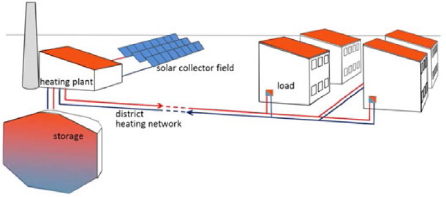
One form of this concept is the centralized solar district heating (SDH) networks where the solar field is often installed near the main DH plant, which contains the supplementary energy system (Figure 1). Ground-mounted flat plate collector is the most used type in the European market of centralized SDH networks with more than 90% of the total installed collector area [12]. Most solar fields in the case of centralized SDH are added to existing DH systems, unlike block heating networks, to reduce the dependency on fossil fuels in the main heating plant.
Scheme of a centralized SDH network at a DH plant [3]
Yang et al. [13] studied the impacts of integrating solar thermal systems with short and long-term centralized thermal energy storage on the overall performance of a solar district heating network. Lozano et al. [14] presented the results of an economic assessment of solar district heating plants in Spain that focused on large-scale DH systems with seasonal storage only. The authors found that less solar collector area is needed with a higher ratio between storage volume and solar collector area.
Urbaneck et al. [15] conducted a technical and economic simulation of conventional DH networks in east Germany and found that a solar fraction of around 10% is easily achievable. The authors admitted that this solar fraction does not meet the aspirations of solar heat specialists. However, they claimed that this solar fraction could be a reasonable baseline to start at in many German DH plants for further improvements.
Bauer et al. [16] studied the integration of solar field and seasonal thermal storage in an existing DH network in Germany and found that a combination of the two systems could be technologically and economically viable for designs with solar fraction above 50%. It was also concluded that the seasonal thermal energy stores offer considerable potential for cost reduction and plant efficiency enhancement.
In the Mediterranean region, Andreu et al. [17] investigated solar heat cost for SDH system with pit thermal energy storage in a city in Croatia. It was indicated that SDH network with underground thermal energy storage is a promising technology for implementation in the Mediterranean areas where the population density is low-to-medium. Tulus et al. [18] also reported similar findings for Mediterranean climate regions. Other studies emphasized the potential benefits of producing hot water with relatively constant outlet temperature when integrating PTC with FPC [19].
In Jordan, an economic study of the hybrid system that consists of a boiler and solar thermal system showed that using solar water heaters for space heating and domestic hot water is cost-effective with a payback period of 3 years but this study was limited to small scale systems only [20].
This study introduces an in-depth theoretical analysis to simulate the process of integrating a solar field in the existing DH at Jordan University of Science and Technology (JUST) which is located in Northern Jordan, in an attempt to minimize the dependency on fossil-based fuels as a source of heating on a large scale. A detailed calculation was conducted to study the potential of utilizing solar heat for space heating. The environmental aspect was also taken into consideration. Additionally, the economic feasibility of this approach was analyzed based on the payback period model.
The novelty of this work lies in the uniqueness of the performance, economic, and environmental impact comparisons between ETC and PTC for district heating purposes. To the best of authors’ knowledge, there are no similar studies that examine the potential of utilizing solar district heating systems under Jordanian climatic conditions. In addition, Jordan’s conditions and the site considered in this study resemble those in vast areas in the region. As such, this study can provide a base on which future studies can be conducted in areas where thermal load patterns are similar to those considered in this work and where the energy supply is in a good match with the demand.
The theoretical simulation model of the integration of solar thermal system in the existing DH network at JUST was carried out utilizing MATLAB software. The model is based on average fuel consumption over the last three years. Hourly solar radiation data were also averaged over the past three years and were imported from PVGIS [21] for JUST specific location. Additional weather data including ambient temperature were provided by the DH network operation engineers at the university using measured values. Key performance indicators in this study included solar fraction (SF), CO2 emission reduction, and the discounted payback period (DPP) of the investment.
The heating system considered here is located on the campus of JUST, in Irbid (32.483380°N, 35.976932°E). It works in such a way that in the heating season (November through March) when the hourly measured ambient temperature is less than 20°C, the DH system provides space heating for most classroom complexes, administration offices, laboratories, library, and student activity complex (gymnasium). The official working hours of the university are 8 am to 4 pm, 5 days a week. The first measurement of ambient temperature is taken at 7 am where the system is set to starts working if the temperature is lower than the specified temperature to allow the buildings to be heated by the time students and staff arrive.
The main components of the heating system are a large-scale heating plant, hot water distribution network, pumping stations, and substations that consist of heat exchangers, and subnetworks to carry the heat generated to the classrooms, offices, and other facilities.
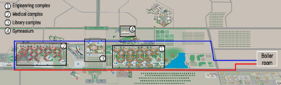
The heating network covers four main areas in the university: the engineering complex, the medical complex, the library complex (which consists of 3 buildings), and the gymnasium. Figure 2 shows a schematic diagram of the areas covered by the existing heating system at JUST where the red and blue lines represent the supply and return pipelines, respectively.
A simplified schematic diagram of the existing DH network at JUST
The heating plant consists of a diesel-fired boiler with a capacity of 18.6 MW. Based on measured values, the boiler outlet supply water temperature ranges from 120 °C and 125 °C, and the return temperature is between 100 °C and 105 °C. Hot water is supplied to the network in the compressed liquid phase since the pumping stations increase the hot water pressure to 23.2 bar where the saturation temperature (Tsat) of water is around 220 °C. Diesel oil consumption of the boiler was calculated by taking the average over the last three years. It turned out that the annual diesel oil consumption was 713,153 L with average operation hours of 550 h/year as provided by the plant operation engineers.
The length of the distribution network is more than 6 km with varying piping diameter. Piping diameter starts at 500 mm at the exit of the boiler room and keeps decreasing until it reaches 100 mm at the inlet of the boiler room. There are 5 pumping stations in the DH network.
Hot water is pumped in the network to deliver thermal energy to the substations, where it exchanges heat with colder water. There are 18 substations in the university buildings with different heat exchanger capacities. As the exact data of heating load and detailed hourly heating demand were unavailable, the design of the solar thermal system in this work was based on the summation of heat exchanger capacities which was determined to be 14.2 MW.
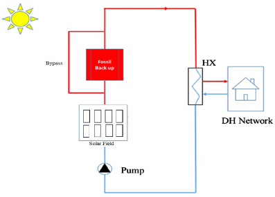
The proposed system in this research is illustrated in Figure 3 that shows the components and their arrangement thereof. A simulation study on different solar collector types and several solar collector areas was undertaken. The main goal was to generate heat utilizing a renewable source as a supplementary source to raise the water temperature to 120 °C or more. The rationale in this study entailed that if the supplied water from the solar field exceeds this temperature, the boiler will not work, otherwise, the boiler will run until the water temperature reaches 120 °C.
Schematic diagram of the proposed system
In an attempt to make this research more comprehensive, two different integration scenarios were considered. The first scenario involved a non-concentrating solar thermal system, while the other was a concentrating solar thermal system. Although flat plate collector type is the most common technology used in DH networks, it was not considered in this work due to its lack of ability to achieve the required water temperature. Instead, evacuated tube collector (ETC) type was used in this study as a non-concentrating solar thermal system since this type can heat water to the desired temperature [22]. For the concentrating solar thermal system scenario, the parabolic trough collector (PTC) was chosen because it is the most cost-effective technology among this category [23].
As the average global irradiance imported from PVGIS is given in 10 min steps, the resolution was reduced to hourly steps in order to use the actual DH return temperature as collector inlet temperature Ti while using the DH supply temperature as the collector outlet temperature Tout. The ambient temperature Ta was taken from PVGIS as well. The efficiency of the ETC, ηc, was calculated according to the European Standard EN 12975 [24] as follows:
(1)
(2)
The collector dependent values η0, a1 and a2 were taken from collector datasheets of a Linuo Ritter (U 1521) evacuated tube collector (ETC) [25].
For the PTC scenario, all equations used were taken from [26]. The PTC model used in this research was (Polythrough 1800) manufactured by NEP Solar company [27]. Collector efficiency factor (F’) is the ratio of actual useful energy collected to the useful energy collected if the entire absorber surface is at the mean fluid temperature and is given by the following equation:
(3)
The heat removal factor, having a value between 0 < FR < 1, can be interpreted as the ratio of the actual useful energy collected to that which would be collected if the entire absorbed surface is at the temperature of the fluid entering the collector. FR is a measure of the efficiency of the receiver when viewed as a heat exchanger, that is, the effectiveness with which the absorber radiation energy is transferred to the working fluid. Its value is governed by the working fluid flow rate and its properties as well as the thermal properties of the receiver material and can be calculated from the equation:
(4)
The useful heat gain, Qu, delivered by the receiver can be conveniently written in terms of the inlet fluid temperature by means of heat removal factor FR as:
(5)
The useful heat is related to the flow rate, specific heat capacity and the fluid temperature difference between the inlet and the outlet. Based on the useful heat, the fluid exit temperature can be calculated as:
(6)
This study was based on different solar field sizes. In the ETC scenario, six areas were considered, starting with 3,000 m2 with an increment of 1,000 for the next area until an aperture collector area of 8,000 m2 is reached. This selection approach was adopted to study a wide range of ETC aperture areas.
For the PTC scenario, however, a different approach was adopted based on the number of loops within the solar field rather than the total collector aperture area due to the simplified representation purpose. Five different numbers of loops were studied: 15, 18, 20, 22, 25. The PTC field area was between 2,576 m2 for the 15 loops case, and 4,294 m2 for the last case. All performance indicators in this study were calculated for each collector type and solar field area.
The term solar fraction (SF) may be defined as the amount of thermal energy produced by the solar thermal system divided by the total thermal energy required. In this study, and for the sake of simplicity, it was assumed that the boiler produces the same amount of thermal energy for every operation hour. It was also assumed that the boiler consumes the same quantity of diesel oil for every operation hour. On JUST’s campus, the boiler is the only source of heat in the DH network. Given that the average boiler annual working hours in the previous years was 550, the annual SF was calculated as follows:
(7)
In this work, the environmental aspect was expressed in terms of savings in CO2 by consuming less diesel oil as a result of the contribution of the solar field to the heating demand in the university. Jordan is responsible for 0.07% of the total CO2 emission in the world as Jordan emits more than 24 million tons of CO2 annually [28]. In a previous study conducted at JUST, CO2 emission due to diesel oil usage was calculated based on the US Environmental Protection Agency (EPA) and US Department of Transportation (DOT) joint report published in 2010, due to the lack of verified values in Jordan [29]. Consequently, CO2 emission savings were expressed as:
(8)
The economic aspect in this work covers all potential costs associated with solar field integration. The initial costs for ETC and PTC were quoted from a well-known local energy company called “Millennium Energy Industries” which imports products from foreign manufacturers. The capital cost of ETC solar collectors in this research ranges from about 225 to 255 USD/m2 depending on the collector area. On the other hand, PTC systems are known to be more expensive than ETC [30]. The PTC quoted price in this study was about 425 USD/m2.
After installing the solar thermal system whether it is ETC or PTC, the boiler would run for fewer hours per year, thus, the boiler would cost less to operate and maintain. The current O&M cost of the boiler is approximately 18,110 USD/year according to the heating plant engineers at the university. Given the very small fraction of O&M costs, it may safely assumed that the boiler O&M cost is distributed evenly on the 550 working hours, the potential savings of the boiler O&M can be calculated using the following formula:
(9)
In the ETC scenario, quoted prices showed that the system O&M annual cost is between 1.4 USD/m2 and 2.2 USD/m2. The O&M cost for PTC was taken to be similar to the one in the Shams-1 PTC plant in the United Arab Emirates [31]. Although Shams-1 plant is a power generation plant, the solar field components are the same. Therefore, after re-scaling the cost based on the collector area, the annual PTC O&M cost becomes 7.3 USD/m2.
The annual savings can be calculated when subtracting the expenses all year round from the summation of savings after making the suggested modifications in this research. The major savings source is the reduction of diesel oil consumption. The university has been purchasing diesel oil at an average price of 0.85 USD/L for the last few years.
The discounted payback period (DPP) can be defined as the period required to reach the break-even point based on a net present value (NPV) of the cash flow. Compared to simple payback period, DPP enjoys the advantage of accounting for the time value of money. It also reflects the amount of time necessary to break-even in a project-based not only on what cash flows occur. DPP was calculated using the following equation [32]:
(10)
In light of the substantial investments required for the proposed modifications in this work, it was decided to utilize the DPP to ensure more accurate assessments. The discount rate was taken to be 8% based on similar projects [31]. Also, it was assumed that the solar system will last for 25 years.
In this work, solar irradiance (G) data were imported from PVGIS [21] for JUST campus location, and the average ambient temperatures (Ta) of each month were taken from measured values given by the existing heating plant. Figure 4 provides all-year-round data for both irradiance and ambient temperatures.
Data of irradiance and ambient temperatures for JUST campus
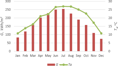
Based on the rationale of this research, it was assumed that the need for space heating exists when the average monthly temperature is less than 20 °C. In other words, the DH system in the university is assumed to work for five months, from the beginning of November till the end of March. The hourly ambient temperatures were given by the heating plant at JUST which were used to calculate the hourly outlet temperatures of the solar field.
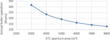
The results for the ETC wil be presented first. For each of several ETC aperture areas, the data about boiler operation hours, solar fraction, amount of diesel oil liters saved, and CO2 emission savings were calculated. Figure 5 illustrates the remaining boiler operation hours according to the installed ETC area. The simulation shows that if a solar ETC system with an area of 3,000 m2 was installed, the boiler working hours would drop from 550 to around 316 per year. The operation hours would continue to drop with a larger ETC field until it reaches approximately 130 hours when the ETC area is 8,000 m2.
Remaining boiler operation hours versus the installed ETC area
This drop in boiler working hours resulted in less diesel oil consumption and lower CO2 emissions. The variation of diesel oil savings in liters with the installed ETC area is illustrated in Figure 6. If an ETC field with an area of 3,000 m2 is installed, about 300 thousand liters of diesel oil could be saved. The potential amount of savings increases with the increase of the ETC area. The largest ETC area considered in this research (8,000 m2) would result in saving of almost 550 thousand liters of diesel oil annually.
Variation of diesel oil and CO2 savings with the installed ETC area
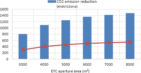
Figure 6 also shows the reduction in CO2 emissions. The results show that installing an ETC system would result in reducing CO2 emissions by 800 to 1,480 metric tons per annum depending on the installed ETC area.
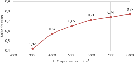
Solar fraction (SF) is one of the most important performance indicators used in this research. SF can indicate the relative contribution of the solar field to the total thermal energy generated for heating purposes. Figure 7 illustrates the SF achieved when a certain ETC area is installed. Results show that the proposed system configuration could attain a SF value of up to 0.77. In other words, if 8,000 m2 of ETC were installed, the solar system would provide around 77% of the total heat needed by the DH network at JUST campus. Figure 7 also shows a slight increase in SF when high values are reached compared to larger increments at lower ETC area. The main cause of this behaviour is the low solar radiation in the morning hours when the ETC system alone is insufficient to meet the heating demand.
Solar fraction versus the ETC area
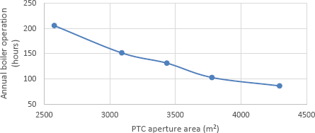
Similar to the ETC, the findings for the PTC case pertain to boiler operation hours, solar fraction, amounts of savings in diesel oil, and reductions in CO2 emissions for different aperture areas of PTC. Figure 8 depicts the remaining boiler operation hours for each studied scenario. The aperture area was calculated for each number of loops, and the performance model was based on the aperture area. For instance, if 15 PTC loops with a total aperture area of 2,576 m2 were installed, the boiler in the heating plant would work for only 205 hours instead of 550 hours yearly. This number would continue to decrease until it drops to 86 boiler operation hours when 25 PTC loops with an aperture area of 4,294 m2 are implemented.
Remaining boiler operation hours versus the PTC aperture area
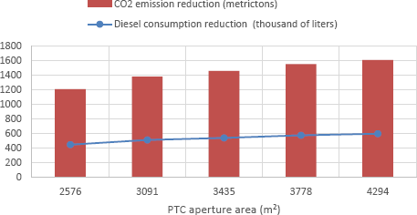
For the PTC capacities considered in this research, diesel oil consumption reduction ranged between 450 and 600 thousand liters per year as shown in Figure 9. Consequently, installing a 4,300 m2 PTC system would result in CO2 savings of more than 1,600 metric tons annually.
Variation of diesel oil and CO2 savings with the installed PTC area
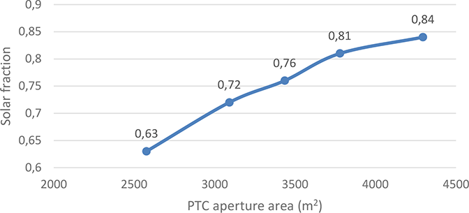
Simulation results show that a higher solar fraction could be achieved in the PTC scenario compared to ETC. Figure 10 demonstrates the achieved solar fraction with respect to the PTC aperture area.
Solar fraction according to the PTC area
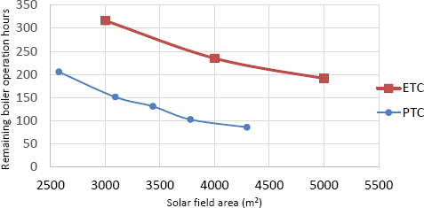
In order to come up with recommendations, a comparison between ETC and PTC technology scenarios was implemented for only solar field areas common to both. The findings show that PTC often offers more advantages over ETC for the same aperture area. Figure 11 shows that the existing boiler and heating system would run for fewer hours in the PTC scenario compared to the ETC scenario for the same aperture areas. The differences in the remaining boiler operation hours between the two technologies are significant. For example, if a PTC solar field with an aperture area of approximately 3,000 m2 is installed, the boiler would work for 150 hours/year, this number would be doubled in the ETC case.
Comparison between ETC and PTC in terms of the boiler remaining operating hours
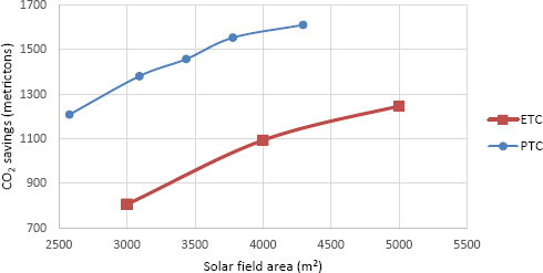
Consequently, using PTC solar technology could result in saving more CO2 compared to ETC of the same aperture area. Figure 12 illustrates the reduction in CO2 emission expressed in metric tons for both ETC and PTC cases.
Comparison between ETC and PTC in terms of CO2 savings
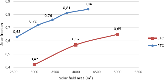
Moreover, installing PTC could be responsible for higher solar fraction compared to ETC. Figure 13 demonstrates the achieved solar fraction in both cases. The comparison shows that for the same aperture area, PTC provides advantages over ETC in terms of the solar fraction, CO2 reduction, and boiler operation hours reduction.
Comparison between ETC and PTC in terms of the achieved solar fraction
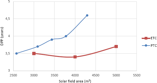
The payback period may be regarded as one of the most important findings in this research. The DPP model was considered and applied in this work. Figure 14 shows the DPP for both ETC and PTC based on aperture area. For the common range between the two solar technologies considered in this work, ETC showed better economic behaviour than PTC. The DPP for ETC ranged between 3.4 and 3.7 years compared to 3.5 and 4.6 years for PTC. In addition, the optimum solar system configuration with respect to the DPP was the ETC with an aperture area of 4,000 m2 that has a DPP of 3.4 years.
DPP for both ETC and PTC if the solar field only is installed
The results show that the integration of a solar system in the existing DH network on JUST campus is an attractive investment due to the low payback periods of the investment. Even though previous studies claimed that solar district heating systems with a high solar fraction (>50%) can’t be economically viable unless seasonal energy storage is added in Europe [33], this study proved that achieving a high solar fraction without the need of thermal energy storage is economically feasible under Jordanian climatic conditions due to the high solar radiation and due to the matching between supply and demand for the case of JUST’s DH network.
In this paper, a study on integrating solar thermal systems in existing district heating systems in Jordan University of Science and Technology campus (Northern Jordan) was assessed in the light of three main aspects: technical, environmental, and economic. Based on the findings herein, it may be stated that there is a promising potential for utilizing solar thermal systems for large scale heating systems under Jordan’s weather. By adopting the suggested scenarios, a high solar fraction up to 0.84 can be achieved without energy storage, and the boiler operation hours can be dramatically reduced with savings in diesel oil of up to 600 thousand liters. This reduction would cut down CO2 emission by up to 1,600 tons annually which accounts for 0.006% of the total CO2 emissions in Jordan. From an economic perspective, results suggest an attractive investment with a relatively low DPP of 3.4 years in the best-case scenario and that PTC technology is superior to ETC technology. However, ETC scenarios have a lower DPP due to the high initial cost of PTC. The study definitively answers the question regarding whether integrating solar systems in existing DH networks is considered an attractive investment to universities and cities with similar heating system properties, weather conditions, and heat load patterns.
It is recommended that future research considers other solar thermal technologies such as linear Fresnel technology technically, environmentally, and economically and compare it with the solar technologies addressed in this work. Also, further research should be carried out to study the impact of adding a thermal energy storage system to the proposed system in terms of performance and economic viability. It would be promising if a future study is conducted to simulate replacing the existing boiler with a modular one that can be adequate to supply the remaining heating demand after installing the solar thermal system.
Aa |
collector aperture area |
[m2] |
Ar |
receiver area |
[m2] |
a1 |
first degree coefficients of the collector heat losses |
[W/K m2] |
a2 |
second degree coefficients of the collector heat losses |
[W/K m2] |
Cp |
specific heat capacity |
[J/kg K] |
D0 |
receiver outside tube diameter |
[m] |
Di |
receiver inside tube diameter |
[m] |
F’ |
collector efficiency factor |
[-] |
FR |
heat removal factor |
[-] |
G |
global radiation |
[W/m2] |
hfi |
convective heat transfer coefficient inside the receiver tube |
[W/K m2] |
m̅ |
mass flow rate |
[kg/s] |
S |
absorbed solar radiation |
[W/m2] |
Tsat |
saturation temperature |
[°C] |
Tm |
hourly medium collector temperature |
[°C] |
Ta |
hourly ambient collector temperature |
[°C] |
Tout |
hourly collector outlet temperature |
[°C] |
Ti |
hourly collector inlet temperature |
[°C] |
UL |
overall heat transfer coefficient |
[W/Km2] |
ΔT |
difference between supply and return temperature |
[°C] |
ηc |
collector efficiency |
[-] |
η0 |
collector zero-loss efficiency |
[-] |
DH |
District Heating |
DHW |
Domestic Hot Water |
DPP |
Discounted Payback Period |
ETC |
Evacuated Tube Collector |
JUST |
Jordan University of Science and Technology |
O&M |
Operation and Maintenance |
PTC |
Parabolic Trough Collector |
ST |
Solar Thermal |
SDH |
Solar District Heating |
- ,
Current status and future investment potential in renewable energy in Jordan: An overview ,Heliyon , Vol. 6 (2),pp e03346 , 2020, https://doi.org/https://doi.org/10.1016/j.heliyon.2020.e03346 - ,
Individual Heating systems vs. District Heating systems: What will consumers pay for convenience? ,Energy Policy , Vol. 86 ,pp 73-81 , 2015, https://doi.org/https://doi.org/10.1016/j.enpol.2015.06.024 - ,
Solar district heating and cooling : A review ,Int. J. Energy Res. , (August),pp 1-23 , 2017 - ,
District heating and cooling : Review of technology and potential enhancements ,Appl. Energy , Vol. 93 ,pp 2-10 , 2012, https://doi.org/https://doi.org/10.1016/j.apenergy.2011.04.020 - ,
Economic Assessment of Rural District Heating by Bio-Steam Supplied by a Paper Mill in Canada ,Bull. Sci. Technol. Soc. , Vol. 28 (2),pp 159-173 , 2008, https://doi.org/https://doi.org/10.1177/0270467607313953 - ,
The role of a paper mill in a merged district heating system ,Appl. Therm. Eng. , Vol. 23 ,pp 769-778 , 2003, https://doi.org/https://doi.org/10.1016/S1359-4311(03)00018-8 - ,
Integrating renewable sources of energy into an existing combined heat and power system ,Energy , Vol. 31 ,pp 2499-2511 , 2006, https://doi.org/https://doi.org/10.1016/j.energy.2005.11.003 - ,
Test and evaluation of a method to identify heating system malfunctions by using information from electronic heat cost allocators ,Energy Build. , Vol. 184 ,pp 152-162 , 2019, https://doi.org/https://doi.org/10.1016/j.enbuild.2018.12.004 - , , in Reference Module in Earth Systems and Environmental Sciences, 2013
- ,
Solar energy - a realistic option for district heating ,Euroheat Power/Fernwarme Int , Vol. 30 , 2001 - ,
SOLAR HEAT WORLDWIDE 2013 Solar Heat Worldwide Markets and Contribution to the Energy Supply, 2013 Edition, 2015 IEA Solar Heating & Cooling Programme, AEE-Institute for Sustainable Technologies A-8200 Gleisdorf, Austria ,pp 66 , 2015 - , EU Handbook District Heating Markets, Intelligent Energy Europe Programme, 2012
- ,
Smart Thermal Grid with Integration of Distributed and Centralized Solar Energy Systems ,Energy , 2017, https://doi.org/https://doi.org/10.1016/j.energy.2017.01.114 - ,
Simulation study and economic analysis of large-scale solar heating plants in Spain ,EUROSUN 2010 , 2010, https://doi.org/https://doi.org/10.18086/eurosun.2010.05.04 - ,
Solar district heating in East Germany - Transformation in a cogeneration dominated city ,Energy Procedia , Vol. 70 ,pp 587-594 , 2015, https://doi.org/https://doi.org/10.1016/j.egypro.2015.02.164 - ,
Solar District Heating for the Built Environment Technology and Future Trends within the European project ,Energy Procedia , Vol. 57 (0),pp 2716-2724 , 2014, https://doi.org/https://doi.org/10.1016/j.egypro.2014.10.303 - ,
Evaluation of integration of solar energy into the district heating system of the city of Velika Gorica ,Therm. Sci. , (January), 2016 - ,
Enhanced thermal energy supply via central solar heating plants with seasonal storage: A multi-objective optimization approach ,Appl. Energy , Vol. 181 ,pp 549-561 , 2016, https://doi.org/https://doi.org/10.1016/j.apenergy.2016.08.037 - ,
Analysis and validation of a quasi-dynamic model for a solar collector field with flat plate collectors and parabolic trough collectors in series for district heating ,Energy , Vol. 142 ,pp 130-138 , 2018, https://doi.org/https://doi.org/10.1016/j.energy.2017.09.135 - ,
Economical investigation of an integrated boiler-solar energy saving system in Jordan ,Energy Convers. Manag. , Vol. 51 (8),pp 1621-1628 , 2010, https://doi.org/https://doi.org/10.1016/j.enconman.2009.08.040 - PV GIS., http://re.jrc.ec.europa.eu/pvgis/apps4/pvest.php#
- , , CIT Energy Management AB, 2010
- ,
The potential of solar industrial process heat applications ,Appl. Energy , Vol. 76 (4),pp 337-361 , 2003, https://doi.org/https://doi.org/10.1016/S0306-2619(02)00176-9 - ,
A Guide to the Standard En12975 - Quality assurance in solar heating and cooling technology ,Intell. Energy Eur. , 2012 - ,
, Forced circulation systems - pressurized U 1521. , http://www.linuo-ritter-international.com/products/solar-collectors/vacuum-tube-collectors/u-pipe-solar-collector/ - , , Solar Energy Engineering: Processes and Systems, 2009
- ,
Characterization of a parabolic trough collector for process heat applications ,Energy Procedia , Vol. 57 ,pp 2804–2811 , 2014 - , , Ministry of Environment and United Nations Development Programme, 2014
- ,
Environmental sustainability features in large university campuses: Jordan University of Science and Technology (JUST) as a model of green university ,Int. J. Sustain. High. Educ. , Vol. 20 (2),pp 214-228 , 2019, https://doi.org/https://doi.org/10.1108/IJSHE-06-2018-0102 - ,
Thermo-economic optimization of a hybrid solar district heating plant with flat plate collectors and parabolic trough collectors in series ,Energy Convers. Manag. , Vol. 165 (October 2017),pp 92-101 , 2018, https://doi.org/https://doi.org/10.1016/j.enconman.2018.03.034 - ,
Techno-economic assessment of substituting natural gas based heater with thermal energy storage system in parabolic trough concentrated solar power plant ,Renew. Energy , Vol. 75 ,pp 152-164 , 2015, https://doi.org/https://doi.org/10.1016/j.renene.2014.09.025 - ,
, Engineering Economy , 2005 - ,
Evaluation of the potential of large solar heating plants in Spain ,Energy Procedia , Vol. 30 ,pp 839-848 , 2012, https://doi.org/https://doi.org/10.1016/j.egypro.2012.11.095