


High efficiency and reliability are major requirements in the hydropower industry. However, the diversity of energy production which needs to match the power demand to achieve grid balance, requires operation over a wide range of water flow and head variations [1]. Consequently, difficulties in maintaining high efficiency, and increased dynamic loads and pressure pulsations can arise under such off-design conditions [2]. The biggest constraint of current hydraulic turbines is the fixed speed operation, which is imposed by the use of synchronous generators [3]. Variable speed operation of Francis turbines can be introduced to improve the efficiency when working at off-design conditions [4]. Additional benefits that can be gained are reducing possibility of draft tube surging and cavitation appearance. Reduced noise, vibration and cavitation problems give advantage of an extended hydraulic turbine service time [5]. For an existing turbine, improvements can be expected with a previous proper hydraulic redesign of its elements [6].
Francis turbines are reaction turbines with main components which consist of runner, spiral casing, stay vanes, guide vanes and a draft tube. Both pressure and kinetic energy is converted into a mechanical energy in the runner [7]. Water enters the runner with optimally designed angle to achieve high efficiency of energy conversion. The inlet angles are provided by the guide vanes to create the necessary circulation in front of the runner since it can be presumed that the circulation of the free fluid flow remains constant from the guide vane exit to the runner inlet [8]. The guide vane outlet angle is designed for the flow rate corresponding to the optimum efficiency. Guide vanes can be opened to a maximum angle appertaining to the full flow rate because of the pivoted support with external control mechanism which allows their continuous movement for regulation of turbine discharge and therefore power. Distributed uniformly in a radial cascade, the guide vanes will direct the water towards the runner and create as uniform as possible flow field with minimal energy losses [9].
Flow entering the runner is greatly influenced by the geometric parameters of the guide vane cascade such as the guide vanes shape, number of guide vanes, pivot axis location and angular position. The choice of guide vane shape is based upon achieving smallest possible losses in the water flow, so it depends on the water approach to the guide vane cascade. In Francis turbines with spiral casing, the inlet end of the blade at optimal opening is arranged to correspond to the water direction from the spiral [8]. Moreover, guide vane shape affects the blade loading. The number of guide vanes is selected to differ from the number of runner blades for preventing periodical flow-rate variations [10]. The position of the axis of guide vane rotation has a great influence on the magnitude of the hydraulic torque acting on the guide vane. The guide vane pivot axis location should provide proper guide vane closing in normal operation, as well as in emergency situations [11]. High efficiency and minimal mechanical loads can be achieved by optimizing these parameters.
The improved computers performance and the advanced numerical modelling give the opportunity to analyze and optimize the water flow inside the complex geometry of Francis turbines, which can be described in terms of parameters [12]. Geometry parametrization is necessary to define a certain number of parameters that represent the part of the turbine needed to be improved. Moreover, it facilitates the fully automatic design generation by modifying the geometry parameters, giving the possibility of defining the optimal design parameters evaluated from CFD results [13]. Gracioano-Uribe et al. [14] emphasize the effects of geometry parameters on turbomachine efficiency which would allow determination of the best geometric configuration based on the criteria of preventing damage caused by instabilities, as a main finding from their profound literature review. Lida et al. [15] parametrized the geometric model of turbine blade by using quintic polynomial method to improve its design quality and performance. Ayli et al. [16] carried out a parametric study to examine the effects of varying selected hydraulic design parameters on the performance of a Francis turbine runner. Optimization using genetic algorithms was performed by Valencia et al. [17] to determine optimal hydraulic parameters of a Francis turbine blade. Iliev et al. [18] suggested an efficient method for parametrizing a Francis turbine blade using low-order Bezier curves. The parametric definition makes the geometries generated for certain input combinations to be suitable for CFD design and optimization. Daneshkah and Zangeneh [19] used a three-dimensional inverse design method to design parametrically defined Francis runner blade geometry. Different design configurations were numerically investigated to evaluate hydrodynamic performance. Ferrando et al. [20] applied parametrization of blade surface based on NURBS curves, linked with automatic mesh generation and fluid flow simulations with k-? turbulence model in NUMECA to determine the hydraulic performance of the generated models. The parametrization was applied to a Francis turbine guide vane. Using objective function, the developed tool proved to be practical in the design optimization process. Tengs et al. [21] developed a fully parametrized variable-speed turbine design procedure in MATLAB. Optimization parameters were reduced to such defining the leading-edge geometry of the blade. Compatibility between the turbine geometry files generated in MATLAB and the ANSYS software used for CFD calculations are ensured, allowing automated geometry creation, mesh generation and simulations of water flow through the turbine components. The authors used the SST turbulence model in ANSYS CFX, defining hydraulic efficiency and mass flow as outputs. High mean efficiency in the range of ±20% of the optimal point is set as an optimization criterion. An increase of 0,25% in mean efficiency compared to a reference case is obtained. Obrovsky and Zouhar [22] optimized the runner blade hydraulic shape in automated cycle using parametrization in ANSYS Blade Generator and simulations in CFX with the k-? turbulence model. Similar procedure was applied by Okyay G. [23]. Using a coupled CFD solver, and parametric geometry and mesh generation tools, Kyriacou et al. [24] proposed a multi-objective redesign of a Francis runner. The efficiency of the hydraulic optimization procedure was validated since the optimal Francis runner design showed higher performance that the initial design regarding all three optimization objectives. Devals et al. [25] presented a hydraulic optimization procedure for developing of a turbine spiral casing and distributor, based on a meta-model assisted evolutionary optimization algorithm, using a mesh generator and a coupled finite volume flow solver. Their approach can take hydraulic performance as well as mechanical stresses into account, with the goal of obtaining a better overall solution. A new optimization method for developing the stay vanes and runner of a Francis turbine with high specific speed was presented by Kawaiiri et al. [26]. A single objective automatic optimization for the stay vane shape, which was defined by many design variables, was carried out. The runner was redesigned with achieving higher efficiency and limiting cavitation appearance. Tengs et al. [27] developed a fully automated multi-disciplinary Francis runner design optimization procedure, both from hydraulic and structural point of view, using MATLAB to produce the design and FSI analysis to evaluate the stresses in the runner blades.
In this paper, as a step towards optimizing the design of a variable speed Francis turbine guide vane, a parametric design tool is established by using coupled MATLAB and ANSYS approach. Additionally, the tool proposes design of the spiral casing and stay vanes ring. According to the previous researchers' findings, applying a blade parametrization as a part of an automated CFD calculation is a practical method for obtaining an optimal blade design. In this research, a MATLAB code was developed to design guide vanes based on parametrization. The guide vane geometry in MATLAB is defined using mathematical functions with their dependent variables used as parameters in the study. Initial guide vane design for given runner geometry is obtained as a product from the MATLAB code. The further analysis takes place in CFD and FEM software through the ANSYS Workbench environment to obtain results for the guide vane hydraulic and mechanical performance. MATLAB is coupled with ANSYS to automate the processes of guide vane geometry generation, meshing, modelling, and simulation. Consequently, this method allows less time-consuming numerical investigation for the purpose of detecting the possibilities for improvement.
The parametric design tool directed towards obtaining an optimal guide vane design is based on the coupling of MATLAB and ANSYS software.
In the case of applying parametrization, the geometry of the turbine component being redesigned should be fully described by a minimal possible number of parameters. In this paper, the parametrization is done for the detailed geometry of the Francis turbine stationary components with emphasis on the guide vane profiles and cascade configuration. A low specific speed Francis turbine was used as a test case for the application of the code.
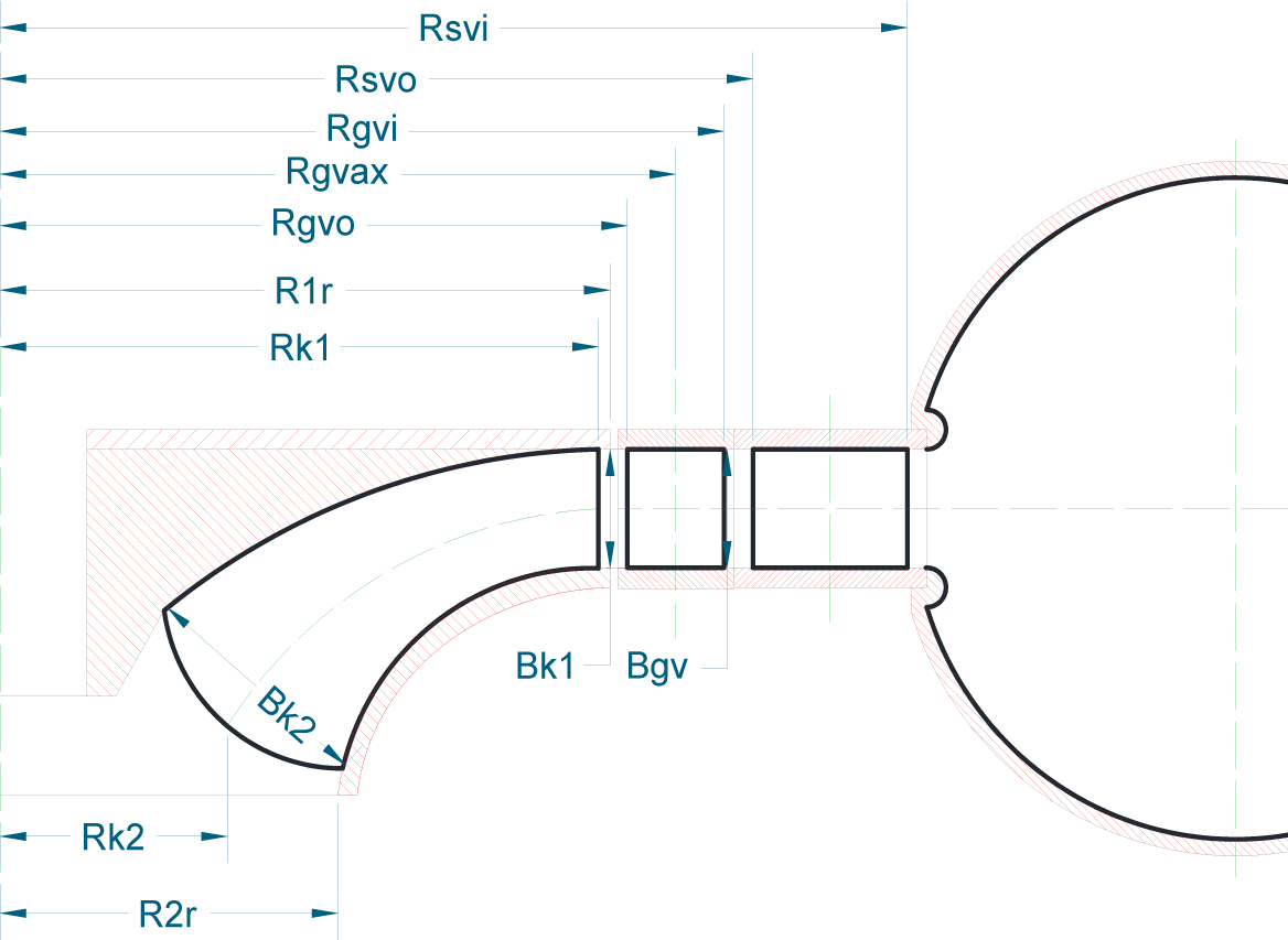
The MATLAB code calculates the velocities at the guide vane inlet and the vaneless space between the guide vane and the runner for the best efficiency point (BEP), based on input parameters related to the turbine operation and the runner geometry, given in Table 1. Known in advance input parameters inserted in the tool are the turbine operating parameters at BEP - head Hn, discharge Q and rotational speed n, and referent geometry parameters such as runner inlet diameter Dr1, guide vane height Bgv and number of guide vanes Zgv. A schematic representation of the main turbine geometrical parameters is shown in Figure 1.
Input and output parameters in MATLAB to obtain guide vane geometry
Input parameters in MATLAB code |
Output parameters from MATLAB code |
|---|---|
Operating parameters in BEP: |
Runner inlet and outlet velocities |
runner speed n [min-1] |
Guide vanes geometry parameters: |
discharge Q [m3/s] |
inlet and outlet diameter [m] |
net head Hn [m] |
axis diameter [m] |
efficiency η [-] |
pitch [m] |
Runner geometry parameters: |
maximum opening angle [°] |
runner inner and outer diameter [m] |
length [m] |
runner blades mid-span inlet |
Guide vanes inlet and outlet velocities: |
diameter [m] |
inlet and outlet meridian velocity [m/s] |
number of blades [-] |
inlet and outlet absolute velocity [m/s] |
runner inlet and outlet height [m] |
inlet and outlet circulation [m2/s] |
runner blade inlet and outlet angle [°] |
inlet and outlet angle [°] |
runner blade inlet and outlet |
guide vane pressure and suction side |
thickness [m] |
contour 2D coordinates |
runner inlet pitch [m] |
Stay vanes outlet angle [°] |
Guide vanes: |
Spiral casing geometry parameters |
height [m] |
|
number of guide vanes |
Schematic representation of geometrical parametrization
The guide vanes are set in a radial cascade, bounded between outlet and inlet circle defined by outlet diameter and inlet diameter calculated as:
(1)
(2)
The pivot axis of every guide vane lies on a circle with axis diameter which can be calculated according to the reduced specific speed number Ω:
(3)
(4)
The ratio of the axis circumference perimeter to the number of the blades in the cascade defines the cascade pitch:
(5)
The radial and peripheral velocity components in front of and behind the guide vane are determined as:
(6)
(7)
(8)
(9)
to obtain the guide vane outlet delivery angle:
(30)
and guide vane inlet flow angle:
(41)
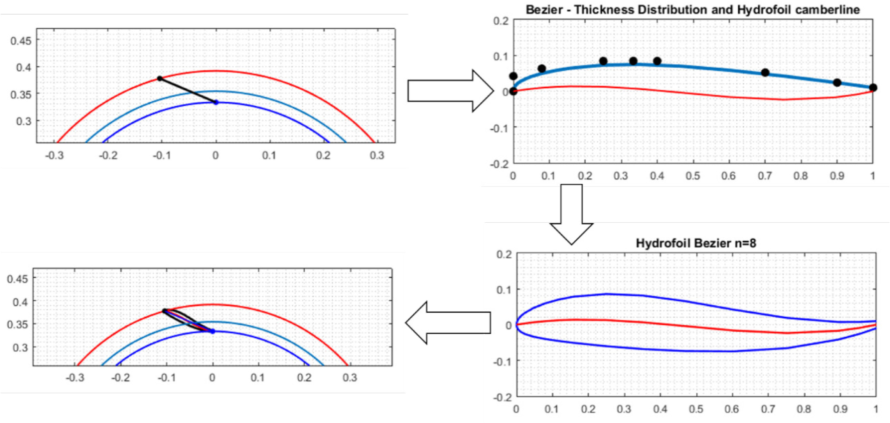
The guide vanes are shaped according to the chord position and the inlet and outlet flow angles. The hydrofoil tail angle β2l and lead angle β1l are calculated for the chord position. The guide vane camber line is mathematically expressed by a third degree polynomial function. Between the ending points on the chord, the camber line is modified and curved for the value of inlet flow angle (leading edge) and outlet delivery angle (trailing edge). Using empirical data, the guide vane thickness distribution is described by Bezier polynomial curves with eight weight points. Having the thickness distribution and the camber line, the guide vane is generated. The guide vane is then positioned in the cascade corresponding to the BEP position by translation, rotation and scaling. The process of guide vane creation in MATLAB is presented in Figure 2.
Guide vane development in MATLAB
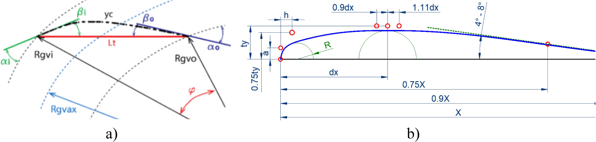
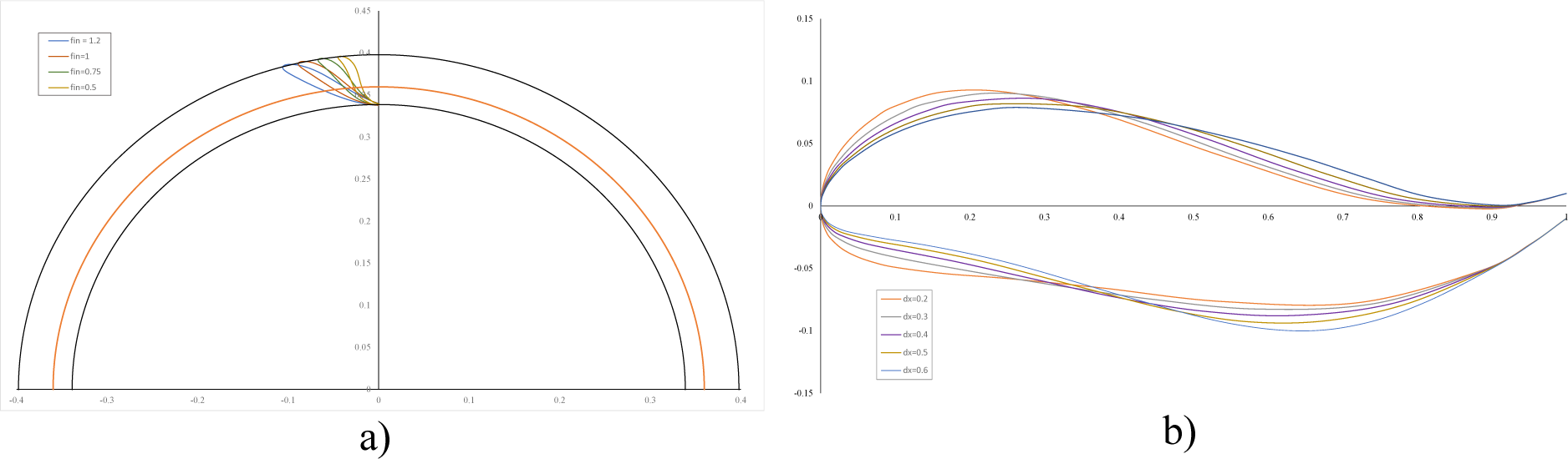
The tool allows flexibility in the guide vane generation by varying the chord line angular position φ and the maximal thickness location on the chord line dx, as shown in Figure 3. The tool uses these parameters as input variables to achieve different guide vane designs which can be further tested and compared.
Flexibility of guide vane design within the parametric tool: a) Camber line creation according to flow angles enclosing with the blade chord line; b) thickness distribution function weight parameters
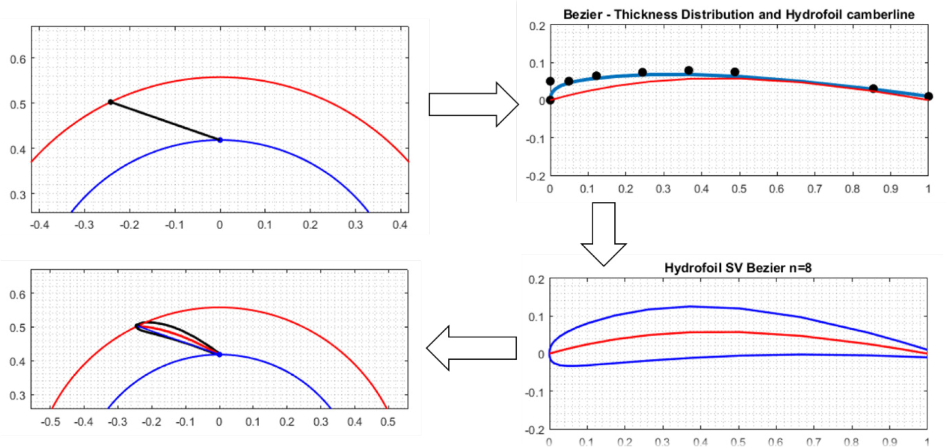
The same methodology is applied to create the stay vanes. According to the runner geometry, stay vanes inlet Dsvi and outlet Dsvo diameters are calculated. Flow conditions at stay vanes outlet and inlet are determined to later obtain the hydrofoil tail angle β2lsv and lead angle β1lsv for the chord position. Obtaining the stay vane camber line and Bezier parametrizing the stay vane thickness distribution with eight weight points, the stay vane is generated (Figure 4).
Stay vane development in MATLAB
The flow rate Qφ through a given section of the spiral described by angle φ is calculated using the total turbine discharge Q and the angle measured from the end of the spiral tooth.
(52)
The water flow rate at the spiral inlet is calculated as:
(63)
Applying the law of constancy of average peripheral velocity:
(74)
where the average velocity in the spiral inlet section depends on the turbine net head and is determined by [8]:
(85)
when Hn < 80 m and
(96)
when Hn > 20 m.
Thus, the area of the corresponding spiral casing section is determined by:
(107)
from which the circles radii can be obtained:
(118)
The spiral casing design which is generated in MATLAB is shown in Figure 5.
Spiral casing development in MATLAB
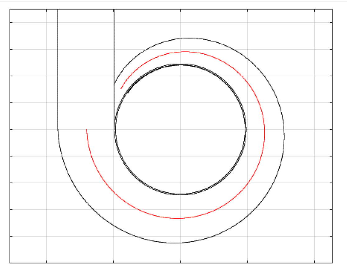
The values of the circles radii and the external, internal and central spiral casing contour are further used in the tool.
The equations used for external, internal and central contour of the spiral casing are calculated by:
(129)
(20)
(21)
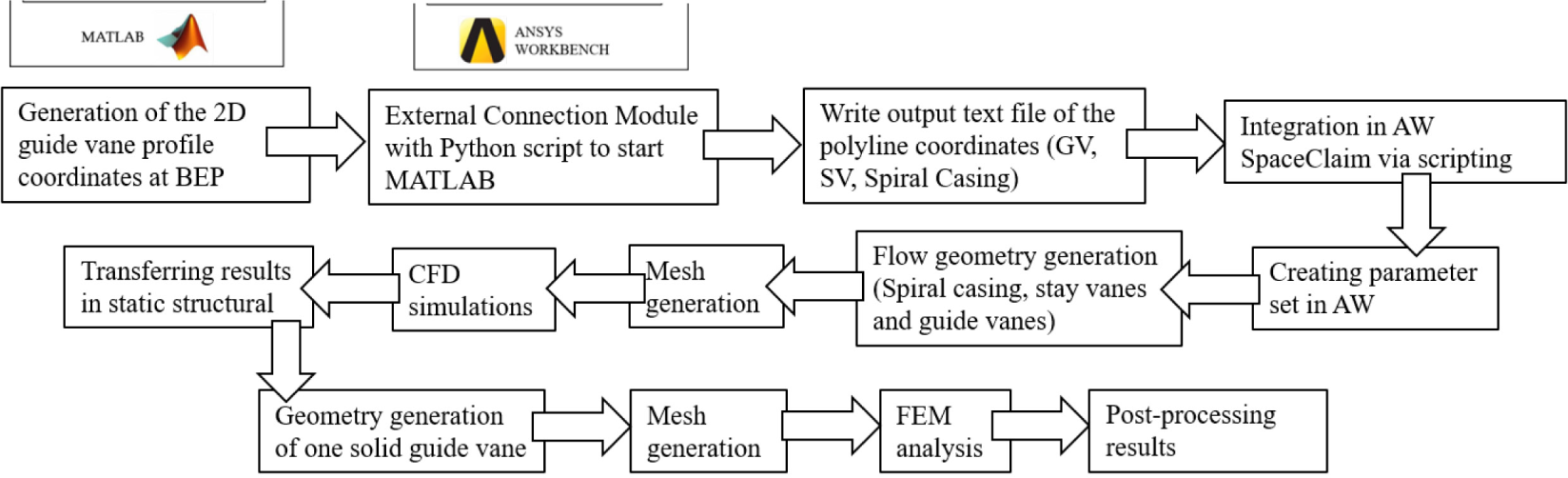
To achieve faster and facilitated guide vane optimization, intended in a next phase, the MATLAB script is created as a function file which can accept inputs and return outputs. In addition, the code is adapted so that it can be run by a Python script to communicate with ANSYS Workbench.
The coordinates of the initial guide vane and stay vane upper and lower curves, so as the coordinates of the spiral casing contours and centerline are MATLAB output, written in a form acceptable to the application for geometry generation SpaceClaim, integrated in ANSYS. Thanks to the journaling and scripting capabilities of Workbench, internal Python scripts are employed in SpaceClaim to automatically generate new guide vane geometry when input parameters are changed. Two SpaceClaim scripts are employed. One script generates the spiral casing, stay vane and guide vane radial cascades according to the following input parameters: turbine discharge, net head, runner rotational speed, runner inlet diameter, guide vane height and number of guide vanes.
This is followed by numerical meshing. Tetrahedral mesh is generated with a predefined value of first cell height of the guide vanes boundary layer Δy1, taken as an output from MATLAB:
(22)
where y+ is user defined value, μ is the water viscosity, ρ is water density, v∞ is the free stream velocity i.e. guide vane inlet velocity and Re is the Reynolds number.
For the generated stationary parts of the Francis turbine, a three dimensional turbulent flow of water at steady state conditions is modelled and simulated.
Output parameters from the simulations can be defined and later used for comparison.
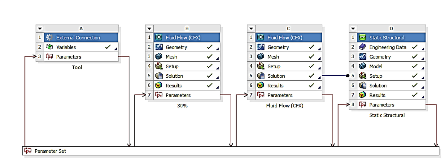
The second script relates to the appropriate design point parameters and generates the geometry of one guide vane. After meshing the geometry, finite element method (FEM) simulations are performed to evaluate stress/displacement conditions. The whole procedure is automated by creating a parameter set in ANSYS Workbench, as shown in Figure 6 and Figure 7.
Established guide vane design tool within ANSYS Workbench
Flow chart of parametric guide vane design tool
Water flow in a Francis turbine with known runner geometry and different new designs of guide vanes is numerically analysed and results from the numerical simulations are compared. The radial cascade of a defined number of new guide vanes at different openings is generated with the SpaceClaim script.
Choosing the Francis-99 turbine model as a test case, the operating conditions, the constraining geometry parameters (number of guide vanes and guide vane height) and the runner geometry, presented in Table 2 were applied.
Constant input parameters for the test cases
Net head Hn [m] |
11.4 |
Design flow rate Qd [m3/s] |
0.21 |
Design rotational speed nd [rpm] |
333 |
Runner inlet diameter Dr1 [m] |
0.62 |
Runner outlet diameter Dr2 [m] |
0.349 |
Guide vanes height Bgv [m] |
0.06 |
Number of guide vanes |
28 |
Three test cases were analysed, by changing the chord line angular position ? and the maximal thickness location on the chord line dx to obtain different guide vane shapes. The chord line angular position was presented in relative terms as normalized angular position ?n:
(23)
By applying the parameters from Table 2 in the tool and varying the normalized chord line angular position φn and the maximal thickness location dx, different guide vanes designs were generated. The first group of designs considers constant location of maximal thickness at 33% of the chord length, while changing the normalized angular position for 0.5; 0.75; 1 and 1.2 whereas the second group of designs considers constant angular chord line position of 1 and variable location of maximal thickness at 20%, 30%, 40%, 50% and 60% of the chord length (Table 3).
Guide vane designs developed according to the variable parameters
Design no. |
1 |
2 |
3 |
4 |
5 |
6 |
7 |
8 |
9 |
|---|---|---|---|---|---|---|---|---|---|
φn |
0.5 |
0.75 |
1 |
1.2 |
1 |
||||
dx |
0.33 |
0.2 |
0.3 |
0.4 |
0.5 |
0.6 | |||
The generated guide vane designs by varying only the normalized angular position, and only the maximal thickness location, are shown in Figure 8a) and b), respectively.
Generated guide vane designs by a) angular chord line position variation, b) maximal thickness location variation
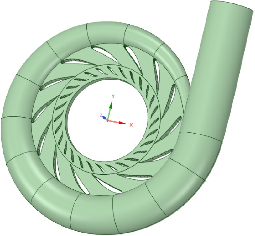
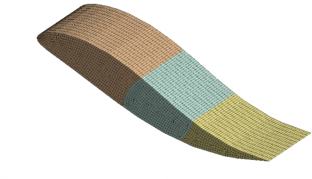
Using the developed 2D curves, the 3D radial cascade of guide vanes is generated. Additionally, the spiral casing and stay vanes ring are created as shown in Figure 9.
Developed geometry of the Francis turbine stationary parts within the tool
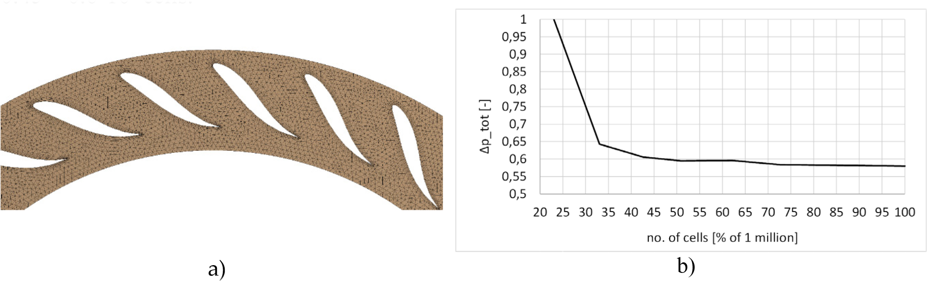
Tetrahedral mesh was used for the fluid geometry (Figure 10a). Element size of guide vane domain was 4 mm. Boundary layer is applied with predefined first cell height calculated within the tool. Mesh independence test was performed for the guide vanes (Figure 10b) observing the total pressure drop through the cascade to obtain low deviations of the total pressure in the guide vane outlet. It was concluded that the guide vanes mesh can consist of 0.45 – 0.6·106 cells.
a) Guide vane domain mesh, b) Grid independence test for the guide vanes domain
For modelling 3D stationary turbulent flow in the hydraulic turbine, k-? turbulence model is selected. The runner speed is defined with the turbine operating conditions. The components of the turbine distributor without the runner are numerically analysed. Initial boundary conditions set in the numerical model are constant total inlet pressure defined by the net head and outlet static pressure. ANSYS CFX is used as a solver. Discretization scheme applied is first order high resolution.
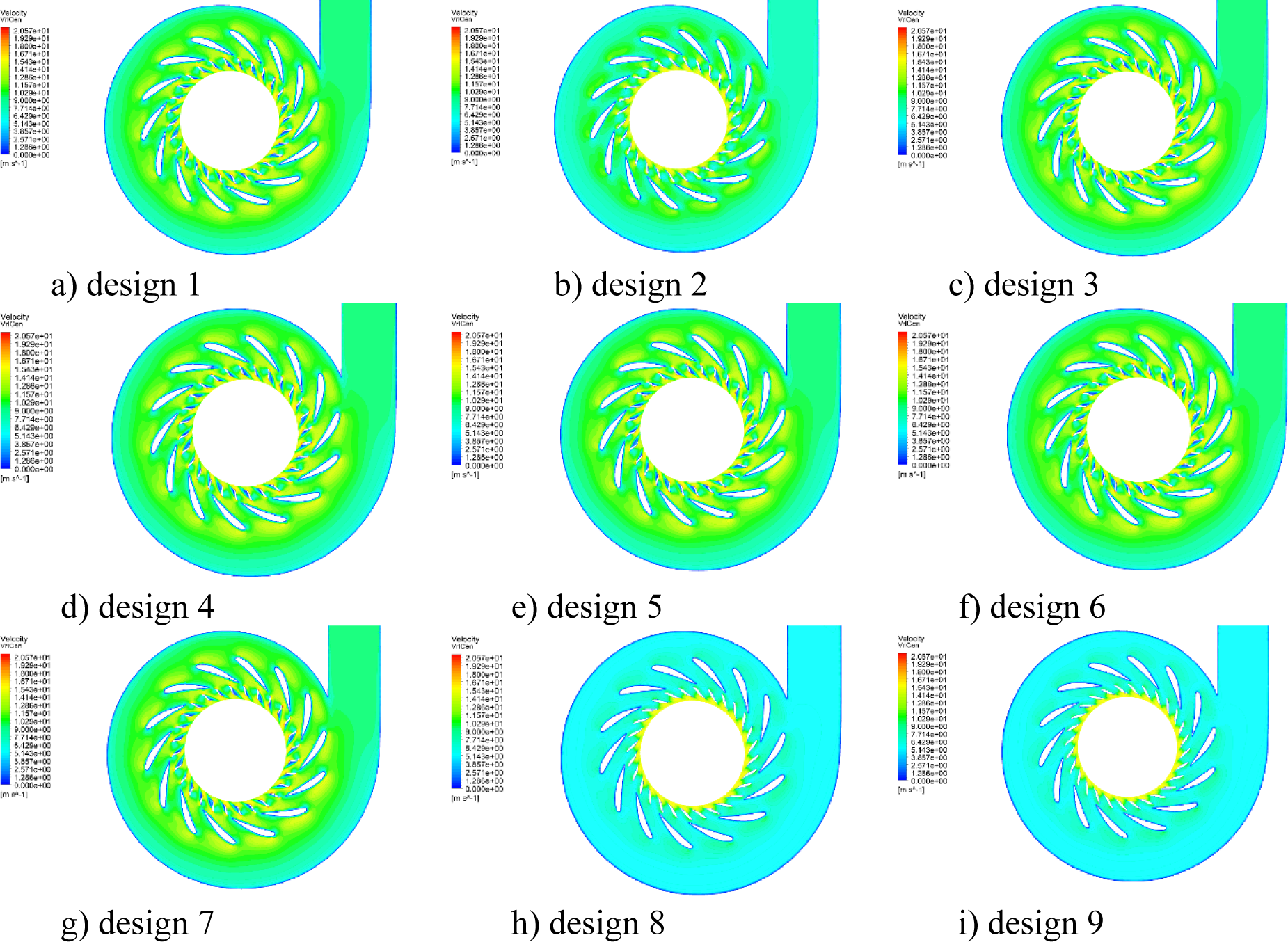
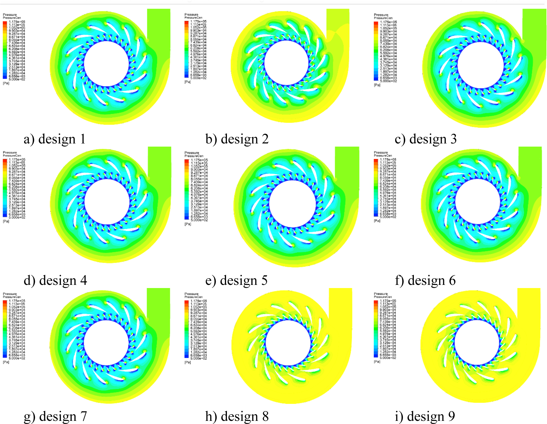
The post-processing allows for analysis and comparison of results between the different guide vane designs (Figure 11 and Figure 12).
Velocity distribution in the Francis turbine model distributor for different guide vane designs
Pressure distribution in the Francis turbine model distributor for different guide vane designs
For the constant head, the mass flow rate obtained for the different guide vane designs is given in Table 4.
Mass flow rate obtained for the designs analysed
Design no. |
1 |
2 |
3 |
4 |
5 |
6 |
7 |
8 |
9 |
|---|---|---|---|---|---|---|---|---|---|
Mass flow rate (kg/s) |
804.96 |
724.78 |
804.9 |
805.6 |
804.7 |
805.1 |
805.4 |
569.7 |
565.6 |
It can be seen that the position of the guide vane in the cascade and the location of its maximal thickness determine the shape of the channel formed between two consecutive blades, which indicates change of the water velocity and pressure distribution.
Guide vane cascades in Francis turbines undergo fluid-structure coupling phenomena. Fluid-structure interaction (FSI) is described by coupling of the equation of motion of the structure and the equation of fluid flow. The CFD calculations are coupled with the FEM simulations in order to determine the overall loads on the guide vane. The loads originate from the water pressure imposed on the guide vane. The pressure distribution obtained from the CFD simulations is applied to the guide vanes surfaces of the finite element model (one-way FSI) as external load. This procedure includes interpolation between the meshes of the fluid domain and the solid domain. Quadrilateral mesh consisting of approximately 71580 elements with size of 1 mm is generated for the guide vane (Figure 13). The static structural analysis does not cover dynamic loads and fatigue, as well as the effects of harmonic oscillations.
Guide vane mesh for static structural analysis
Remote displacement boundary condition is used to account for the shaft with bearings. One guide vane is selected for analysis. The material for the guide vanes is stainless steel with modulus of elasticity 2·105 MPa, density of 7850 kg/m3 and Poisson ratio 0.3.
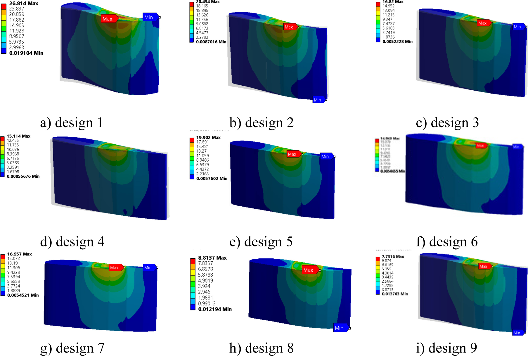
Stress distribution and deformation of guide vane can be analysed within the tool (Figure 14 and Figure 15).
Guide vane stress distribution [MPa]
Guide vane deformation [mm]
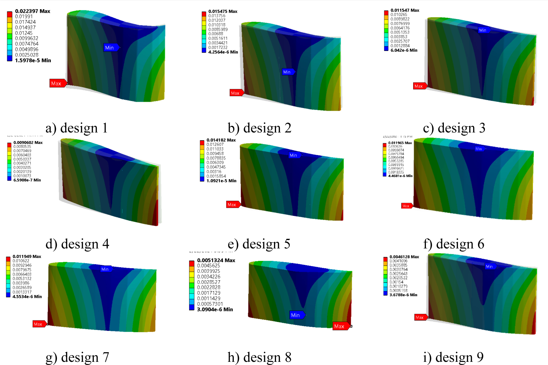
When optimizing the structural design of the guide vane, the critical locations of maximum stress and deformation should be considered. Attention should be paid on the guide vane thickness, trailing edge and the guide vane-shaft contact. The guide vane shape is dominant criterion for the mechanical design, since it determines the blade loading, which affects the guide vanes pressure distribution and consequently the stresses on the guide vane. By changing the guide vane position described by the normalized angular position or the location of the maximal thickness, different blade pressure profile is obtained. This is attributed to the change of the inter-blade channel shape which imposes different hydrodynamic forces. By controlling these parameters, guide vane stresses and deformations can be reduced. Another relevant parameter is the pivot axis location. The position of the pivot axis affects the stresses distribution, and magnitude and direction of the hydraulic torque. This parameter can be further optimized using the design tool by analysing output results for the torque acting on the guide vane, stresses and deformations of the guide vane.
The purpose of this research is showing the possibilities of the developed tool for designing guide vanes of a variable-speed Francis turbine. The tool is based on parametrization which facilitates the process of automating the geometry creation, meshing, modelling and simulation by taking advantages of the software MATLAB and ANSYS Workbench. By inserting the runner geometrical parameters and the turbine operating conditions at constant head, initial guide vane geometry is developed according to variable user-defined parameters. Selected geometrical parameters that affect the guide vane shape and therefore its hydraulic and mechanical performance are the guide vane angular chord line position and the guide vane maximal thickness location. By keeping one of these parameters constant and varying the other one, 9 different guide vanes designs were generated. Simulation of 3D steady water flow in the Francis turbine stationary elements and FEM analysis of a solid guide vane were performed for the developed guide vane designs. The obtained numerical results with application of the parametric guide vane design tool allows for further analysis, comparison between the designs, using optimization schemes in ANSYS WB and making conclusions towards selection of an optimal guide vane design.
This project has received funding from the European Union's Horizon 2020 "Secure, Clean and Efficient Energy" programme, H2020-LCE-07-2016-2017, under grant agreement no 764011. Project: Increasing the value of hydropower through increased flexibility - HydroFlex (
- ,
Integration of variable speed hydropower generation and VSC HVDC, , 2015https://search.abb.com/library/Download.aspx?DocumentID=9AKK10103A6095&LanguageCode=en&DocumentPartId=&Action=Launch - ,
Variable-speed Operation of Francis Turbines: A Review of Perspectives and Challenges, ,Renew. Sustain. Energy Rev. , Vol. 103 (1),pp 109-121 , 2019, https://doi.org/https://doi.org/10.1016/j.rser.2018.12.033 - ,
Maximum Efficiency Point Tracking for Adjustable-Speed Small Hydro Power Plant, , 2008https://citeseerx.ist.psu.edu/viewdoc/download?doi=10.1.1.1022.5530&rep=rep1&type=pdf - ,
Variable-speed Hydro Generation; Operational Aspects and Control, ,IEEE Trans. Energy Conversio , Vol. 12 (2),pp 569-574 , 2006, https://doi.org/https://doi.org/10.1109/TEC.2005.858084 - ,
The Benefits of Variable-speed Operation in Hydropower Plants driven by Francis Turbines, ,Energies , Vol. 12 (19),pp 3719 , 2019, https://doi.org/https://doi.org/10.3390/en12193719 - ,
Hydraulic Optimization of Francis Turbines for Variable Speed Operation using Surrogate Modeling, ,J. Fluids Eng. , Vol. 142 (10), 2020, https://doi.org/https://doi.org/10.1115/1.4047675 - ,
Flow Field Measurement in Guide Vane Cascade of a High Head Francis Turbine, , 2016https://www.researchgate.net/publication/303974944_Flow_field_measurement_in_guide_vane_cascade_of_a_high_head_Francis_turbine - , , Hydraulic Machines - Turbines and Pumps, 1986
- ,
Fail-safe Design and Analysis for the Guide Vane of a Hydro Turbine, ,Adv. Mech. Eng. , Vol. 8 (7),pp 1-8 , 2016, https://doi.org/https://doi.org/10.1177/1687814016658178 - ,
Hydraulic Turbines. Saraevo: University of Sarajevo-Faculty of Mechanical Engineering ,Saraevo , 2016 - ,
, Konstrukcii i raschet gidroturbin , 1974 - ,
CFD-based Casing and Distributor Hydraulic Design Optimization, ,IOP Conf. Ser. Earth Environ. Sci. , Vol. 240 (2), 2019, https://doi.org/https://doi.org/10.1088/1755-1315/240/2/022033 - ,
Optimal design of hydraulic turbine distributor, ,WSEAS Trans. Fluid Mech. 3 , Vol. 3 (2),pp 175-185 , 2008http://www.wseas.us/e-library/transactions/fluid/2008/30-665N.pdf - ,
Instabilities and Influence of Geometric Parameters on the Efficiency of a Pump Operated as a Turbine for Micro Hydro Power Generation: A Review, ,J. Sustain. Dev. Energy, Water Environ. Syst. , , https://doi.org/https://doi.org/10.13044/j.sdewes.d8.0321 - ,
Parametric Design and Simulation Analysis of Turbine Blade, ,Comput. Model. new Technol. , Vol. 18 (11),pp 1223-1228 , 2014http://www.cmnt.lv/upload-files/ns_39art202.pdf - ,
Determination and Generalization of the Effects of Design Parameters on Francis Turbine Runner Performance, ,Eng. Appl. Comput. Fluid Mech. , Vol. 10 (1),pp 545-564 , 2016, https://doi.org/https://doi.org/10.1080/19942060.2016.1213664 - ,
Parametric Optimization to Reduce erosion in a Francis Turbine Runner, ,IOP Conf. Ser. Earth Environ. Sci. , Vol. 240 (2), 2019, https://doi.org/https://doi.org/10.1088/1755-1315/240/2/022041 - ,
Francis turbines for variable speed operation: Parametric definition of Francis turbine blades using low-order Bézier curves, Paper 4, ,Norwegian University of Science and Technology, Faculty of Engineering Science and Technology , 2020 - ,
Parametric Design of a Francis Turbine Runner by Means of a Three-dimensional Inverse Design Method, ,IOP Conf. Ser. Earth Environ. Sci. , Vol. 12 (1), 2010, https://doi.org/https://doi.org/10.1088/1755-1315/12/1/012058 - ,
Surface Parametrization of a Francis Runner Turbine for Optimum Design, , 2004https://hal.archives-ouvertes.fr/hal-00262326/document - ,
Optimization Procedure for Variable-speed Turbine Design, ,Eng. Appl. Comput. Fluid Mech. , Vol. 12 (1),pp 652-661 , 2018, https://doi.org/https://doi.org/10.1080/19942060.2018.1507950 - ,
Experiences with the Hydraulic Design of the High Specific-speed Francis Turbine, ,IOP Conf Ser. Earth Environ. Sci. , Vol. 22 (1), 2014, https://doi.org/https://doi.org/10.1088/1755-1315/22/1/012027 - , Utilization of CFD Tools in the Design Process of a Francis Turbine,, The Graduate School of Natural and Applied Sciences of Middle East Technical University, 2010
- ,
Evolutionary algorithm based optimization of hydraulic machines utilizing a state-of-the-art block coupled CFD solver and parametric geometry and mesh generation tools, ,IOP Conf. Ser. Earth Environ. Sci. , Vol. 22 , 2014, https://doi.org/https://doi.org/10.1088/1755-1315/22/1/012024 - ,
CFD-based casing and distributor hydraulic design optimization, ,IOP Conf. Ser. Earth Environ. Sci. , Vol. 240 (2), 2019, https://doi.org/https://doi.org/10.1088/1755-1315/240/2/022033 - ,
Design optimization method for Francis turbine, ,IOP Conf. Ser. Earth Environ. Sci. , Vol. 22 (1), 2014, https://doi.org/https://doi.org/10.1088/1755-1315/22/1/012026 - ,
Fully automated multidisciplinary design optimization of a variable speed turbine, ,IOP Conf. Ser. Earth Environ. Sci. , Vol. 774 , 2021, https://doi.org/https://doi.org/10.1088/1755-1315/774/1/012031